Hunter 23921 Owner's Manual
Hunter 23921 Manual
 |
View all Hunter 23921 manuals
Add to My Manuals
Save this manual to your list of manuals |
Hunter 23921 manual content summary:
- Hunter 23921 | Owner's Manual - Page 1
For Your Records and Warranty Assistance For reference, also attach your receipt or a copy of your receipt to the manual. Model Name Model No. Date Purchased Where Purchased Type 5 Models Owner's Guide and Installation Manual English Español Form# 42786-01 20090814 ©2009 Hunter Fan Co. - Hunter 23921 | Owner's Manual - Page 2
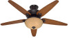
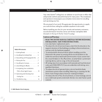
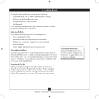
Cleaning Your Ceiling Fan 13 9 • Troubleshooting 14 Welcome Your new Hunter® ceiling fan is an addition to your home or office that will provide comfort and performance for many years. This installation and operation manual gives you complete instructions for installing and operating your fan. We - Hunter 23921 | Owner's Manual - Page 3
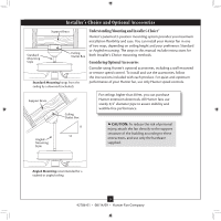
the instructions included with each product. For quiet and optimum performance of your Hunter fan, use only Hunter speed controls. Support Brace Angled Mounting Style Ceiling Outlet Box 8 12 For ceilings higher than 8 feet, you can purchase Hunter extension downrods. All Hunter fans use sturdy - Hunter 23921 | Owner's Manual - Page 4
, contact your Hunter dealer or call Hunter Technical Support Department at 888-830-1326 (In Canada, call 1-866-268-1936). Preparing the Fan Site Before you begin installing the fan, follow all the instructions in the pullout sheet called "Preparing the Fan Site." Proper ceiling fan location and - Hunter 23921 | Owner's Manual - Page 5
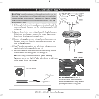
, such as a tag, to the service panel. 2-1. Drill two pilot holes into the wood support structure through the outermost holes in the Ceilings: Be sure to orient the ceiling plate so that the arrows printed on the ceiling plate are pointing toward the ceiling peak. 5 42786-01 • 08/14/09 • Hunter Fan - Hunter 23921 | Owner's Manual - Page 6
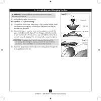
the coating prevents the downrod from unscrewing. Once assembled, do not remove the downrod. 3-4. Raise the fan and place the hook on the ceiling plate through the U-shaped hole in the rim. Steps 3-2 - 3-3 Downrod Canopy Set Screw Step 3-4 U-shaped Hole 6 42786-01 • 08/14/09 • Hunter Fan Company - Hunter 23921 | Owner's Manual - Page 7
through the ceiling plate into the outlet box. 4-7. Spread the wires apart, with the grounded wires on one side of the outlet box and the ungrounded wires on the other side of the outlet box. fsdfsdf Wire Connector Dual Switch Wiring Single Switch Wiring 7 42786-01 • 08/14/09 • Hunter Fan Company - Hunter 23921 | Owner's Manual - Page 8
the ceiling and rotate the fan until each canopy tab engages a groove in the hanger ball. Note: If the tabs are already engaged, do not rotate. Step 5-2 Canopy Steps 5-4 - 5-5 Ceiling Plate Step 5-3 Ceiling Plate Canopy Screw Hanger Ball Canopy Screw 8 42786-01 • 08/14/09 • Hunter Fan Company - Hunter 23921 | Owner's Manual - Page 9
Blades Hunter fans use several styles of fan blade irons (brackets that hold the blade to the fan). 6-1. Your fan may include blade grommets. If your fan has mounting screw through the blade iron, and attach lightly to the fan. Insert the second blade mounting screw, then securely tighten both - Hunter 23921 | Owner's Manual - Page 10
7 • Completing Your Installation With a Bowl Light Fixture Your Hunter fan comes with an integrated light fixture assembly. WARNING: Use only the light fixture supplied with this fan model. The switch housing assembly is made up of three sections: the switch housing gasket, the upper switch housing - Hunter 23921 | Owner's Manual - Page 11
ATTACHING THE LOWER SWITCH HOUSING/LIGHT ASSEMBLY 7-7. Locate the housing screws. NOTE: Depending upon your fan model, these screws may be installed in the four spokes from the switch housing mounting plate screws. Spokes Step 7-7 Housing Screws 11 42786-01 • 08/14/09 • Hunter Fan Company - Hunter 23921 | Owner's Manual - Page 12
breakaway connector on the end of the extra chain.) Fan Pull Chain Breakaway Connector Note: In compliance with US federal energy regulations, this ceiling fan contains a device that restricts the light kit to Pull Chain Glass Bowl 12 42786-01 • 08/14/09 • Hunter Fan Company Cover Plate Finial - Hunter 23921 | Owner's Manual - Page 13
8 • Operating and Cleaning Your Ceiling Fan 8-1. Turn on electrical power to the fan. 8-2. The fan pull chain controls power to the fan. The pull chain has four settings in sequence: High, Medium, and high-gloss blades in the same manner as the fan finish. 13 42786-01 • 08/14/09 • Hunter Fan Company - Hunter 23921 | Owner's Manual - Page 14
blade is cracked. If so, replace all the blades. Problem: Excessive wobbling. 1. If your fan wobbles when operating, use the enclosed balancing kit and instructions to balance the fan. 2. Tighten all blade iron screws. 3. Turn power off, support fan very carefully, and check that the hanger ball is
-
 1
1 -
 2
2 -
 3
3 -
 4
4 -
 5
5 -
 6
6 -
 7
7 -
8
-
9
-
10
-
11
-
12
-
13
-
14
 |
 |
Type 5 Models
Type 5 Models
Type 5 Models
Form# 42786-01
20090814
©2009 Hunter Fan Co.
For Your Records and
Warranty Assistance
For reference, also attach your receipt or a copy
of your receipt to the manual.
__________________________________________
Model Name
__________________________________________
Model No.
__________________________________________
Date Purchased
__________________________________________
Where Purchased
English
Español
Owner’s Guide and Installation Manual