Hunter 25866 Owner's Manual - Page 1
Hunter 25866 Manual
 |
View all Hunter 25866 manuals
Add to My Manuals
Save this manual to your list of manuals |
Page 1 highlights
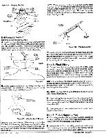
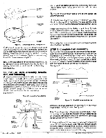
SINCE 1 8 8 6 INSTALLATION INSTRUCTIONS \ FOR HUNTER CEILING FANS USING INSTALLER'S CHOICE MOUNTINGS READ AND SAVE THESE INSTRUCTIONS CAUTION 1. Read entire instruction before beginning installation. 2. Toavoidpossibleelectricalshock,becertainelectricityisshut offatmainpanelbefore wiring. 3. All wiring must be in accordance with national and local electricalcodes. ifyouam unfamiliar with wiring, youshould use a qualified electrician "WARNING. 1. Toreduce theriskoffire orelectricalshock, donotuse a solid state speed control with this fan. Use Hunter Controls only. 2. To reduce the risk ofpersonal injury, do not bend the blade brackets wheninstalling the brackets orcleaning the fan. Do notinsert foreign objectsinbetween the rotating fan blades. Step 1: Pre-installation Instructions A. Select installation site. Check to see that in normal use no object can come in contact with the rotating fan blades. The mounting site should also meetthe precautions listed in step '3 below. B. Installation hardware is included for a standard drywall or plaster ceiling. You will need a 4" x 1-1/2" or a 4" x 1/2" outlet box and wire nuts (2) which can be purchased from any hardware store or electrical supply house. C. The fan blades must be mounted at least 7' above the floor. For maximum efficiency, they should not have any obstruction (walls, posts, etc,)within 24" of the blade tips. See Figure 1for mounting distances. Step 3: installation of Outlet Box and Rough---in Wiring. CAUTION: YourHunterCeiling fanwithaccessoriescanweighup to 35 lbs. The following precautions must be taken for safety and to ensure that your fan is securely mounted to the ceiling. Be certain electricity is 'off' at the fuse panel when inspecting or repairing installation site. All wiring must meet local and national electrical codes.Do not mount directly to an unsupported ceiling or to an electrical outlet box. Mounting must support a 35 lb. fan with accessories. A. Secure metallic outlet box 4" X 1-1/2" or 4" x1/2" deep to 2 X4 cross brace between two ceiling joists as shown in Figure 2. The outlet box must be recessed into the ceiling by 1/16" minimum. Secure the outlet box to the cross brace by drilling (2) pilot holes no larger than the minor diameter of the wood screws (5/64") and use two #8 x 1-1/2" wood screws and washers. Use the innermost holes for securing the box. Orient the box so the outermost holes will be used in step 4B. Caution: Do not use lubricant on screws. 2 X 4 BRACE CEILING JOIST Step 2: Inspection of Fan A. Unpack the fan carefully to avoid any damage to the components. B. Check for any shipping damage to the motor and the fan blades. If more than one fan is being installed, keep the matched and balanced blades in sets, as they were shipped. Should one of the blades become damaged during shipment, return all blades in the set for replacement. C. Check contents to be certain it contains a bag of parts. CEILING OUTLET BOX Figure 2. Outlet Box #8 WOOD SCREW & WASHER (2) REQUIRED B. Bring electrical cable into the outlet box and attach with an approved connector. Make certain that wiring meets all national and local electrical codes. Wire leads should extend at least 6" beyond outlet box•for ease in making connections. See Figure 3. 1 EV MIN. CEILING TO FLOOR 7' MIN. TO FLOOR Form No. 41128 11/93 24" CLEARANCE TO OBSTRUCTIONS no up u u . S. 0 :0 ." U,„0 0 Figure 1. Wall Clearances CONNECTOR Figure 3. Wiring Outlet Box 0 0 0 00 " 0 00 0 ,,00 , :b 00 ri 6" MIN. LEAD LENGTH
-
 1
1 -
 2
2 -
 3
3 -
 4
4 -
 5
5 -
 6
6
 |
 |
