Hunter 25866 Owner's Manual - Page 5
Blade, Assembly, Installa, Balancing, Complete, Assembly
 |
View all Hunter 25866 manuals
Add to My Manuals
Save this manual to your list of manuals |
Page 5 highlights
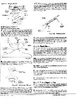
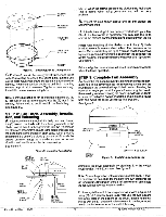
CEILING PLATE MOUNTING SCREWS MOUNTING HOLE MOUNTING SLOTS (2) CANOPY Figure G. Mounting Fan to Ceiling Plate C. Position (2) slots in the canopy directly under and in line with (2) mounting screws in the ceiling plate. Lift fan until ceiling plate mounting screws are seated in bottom slots of canopy. Rotate fan counter clockwise until both mounting screws drop Into slot recesses. Tighten screws securely. Install third screw into mounting hole. Note: For the ball hanging fan configuration make sure the (2) grooves in the ball are engaged with the (2) tabs in the canopy. Failure to do so could result in the fan falling. See figure 5C. • NOTE: When the screws are tight the blades may feel loose. This is normal when using grommets and will not be a problem. B. Repeat the step shown above until all the blades are securely attached. Cp A blade balancing kit has been provided with your fan. Should the fan wobble in operation, you may use the kit to correct the balance per the instructions supplied with the kit. Note: After installing all the blades, check the (10) blade bracket assembly screws which attach the brackets to the motor. Make certain they are tight. You can reach the screws by inserting'a screwdriver intothe openinginthe bottom ofthe switch housing. Rotate the blades to access all (10) screws. See figure 7. Failure to tighten these screws will result in noise and wobble when the fan is operating. STEP 9: Complete Fan Assembly A. Assemble the bottom cover by aligning the small rectan- gular hole in the cover with the fan reversing switch and the round hole in the cover with the pull chain switch. Holding the cover at an angle, you must first place the rectangular hole in the reversing switch and swing the cover up so the round hole is below the pull chain switch. Insert the chain into the round hole and swing the cover up into its final position. See figure 8. STEP 8: Fan Blade Assembly, Installation, and Balancing A. Slide wood blade through slot in belly band and line up the (2) holes in the blade with the rubber grommets in the blade bracket. Insert rubber grommets into the (2) holes in the blade and assemble the blade to the blade bracket using the shoulder screws provide in sack parts. When properly assembled, the end of the blade grommets will fit inside the bracket grommet. snug the shoulder screws to prevent vibration and wobble when the fan is operating. See Figure 7. Figure 7. InstallingFanBlades BLADE BRACKET GROMMET BLADE BRACKET REVERSING SWITCH BOTTOM COVER SWITCH HOUSING PULL CHAIN SWITCH 8 32 SCREW Figure 8. Installing Bottom Cover BELLY BAND MOTOR Complete the cover assembly by attaching it to the switch housing with (3) #8-32 screws. See figure 8. FAN BLADE SWITCH HOUSING Note: Check the position of the reversing switch knob. If it's in the center of the hole slide it to the right for down draft or to the left for up draft. If the switch knob is left in the center of the hole the fan will not operate when turned on. BLADE GROMMET SHOULDER SCREW Form No. 41128 11/93 BLADE BRACKET ASSEMBLY SCREWS (10) B. Assemble the switch housing cover as shown in figure 8A using (2) -32 screws. Make sure you use the two square clearance holes in the bottom of the cover. These holes will line up with the (2) threaded holes closest to the large round hole in the bottom center of the switch housing. 4 ©1993 Hunter Firi
-
 1
1 -
 2
2 -
 3
3 -
 4
4 -
 5
5 -
 6
6
 |
 |
