IBM 2652 Hardware Maintenance Manual - Page 139
to the right side of the, LCD cover.
 |
UPC - 087944815198
View all IBM 2652 manuals
Add to My Manuals
Save this manual to your list of manuals |
Page 139 highlights
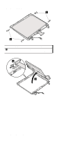
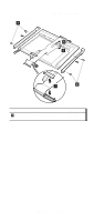
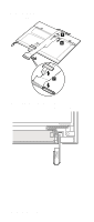
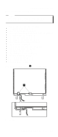
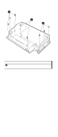
Removing and replacing a FRU When installing the antenna assembly, do as follows: 1. Attach the antenna and route the cable. Note: Attach the gray cable (MAIN) to the left side and the black cable (AUX) to the right side of the LCD cover. 2. Secure the cables with insulation tape in the order shown 1 and 2 . 2 1 (continued) ThinkPad A30, A30p, A31, A31p 135
-
 1
1 -
2
-
3
-
4
-
5
-
6
-
7
-
8
-
9
-
10
-
11
-
12
-
13
-
14
-
15
-
16
-
17
-
18
-
19
-
20
-
21
-
22
-
23
-
24
-
25
-
26
-
27
-
28
-
29
-
30
-
31
-
32
-
33
-
34
-
35
-
36
-
37
-
38
-
39
-
40
-
41
-
42
-
43
-
44
-
45
-
46
-
47
-
48
-
49
-
50
-
51
-
52
-
53
-
54
-
55
-
56
-
57
-
58
-
59
-
60
-
61
-
62
-
63
-
64
-
65
-
66
-
67
-
68
-
69
-
70
-
71
-
72
-
73
-
74
-
75
-
76
-
77
-
78
-
79
-
80
-
81
-
82
-
83
-
84
-
85
-
86
-
87
-
88
-
89
-
90
-
91
-
92
-
93
-
94
-
95
-
96
-
97
-
98
-
99
-
100
-
101
-
102
-
103
-
104
-
105
-
106
-
107
-
108
-
109
-
110
-
111
-
112
-
113
-
114
-
115
-
116
-
117
-
118
-
119
-
120
-
121
-
122
-
123
-
124
-
125
-
126
-
127
-
128
-
129
-
130
-
131
-
132
-
133
-
 134
134 -
 135
135 -
 136
136 -
 137
137 -
 138
138 -
 139
139 -
 140
140 -
 141
141 -
 142
142 -
 143
143 -
 144
144 -
145
-
146
-
147
-
148
-
149
-
150
-
151
-
152
-
153
-
154
-
155
-
156
-
157
-
158
-
159
-
160
-
161
-
162
-
163
-
164
-
165
-
166
-
167
-
168
-
169
-
170
-
171
-
172
-
173
-
174
-
175
-
176
-
177
-
178
-
179
-
180
-
181
-
182
-
183
-
184
-
185
-
186
-
187
-
188
-
189
-
190
-
191
-
192
 |
 |

When installing the antenna assembly, do as follows:
1.
Attach the antenna and route the cable.
Note:
Attach the gray cable
(MAIN)
to the left side and
the black cable
(AUX)
to the right side of the
LCD cover.
2.
Secure the cables with insulation tape in the order
shown
±1²
and
±2²
.
1
2
(continued)
Removing and replacing a FRU
ThinkPad A30, A30p, A31, A31p
135