IBM IC35L020 Hard Drive Specifications - Page 42
CSEL Cable Select Optional, IORDY, DMACK, DMARQ, HDMARDY- Ultra DMA, HSTROBE Ultra DMA
 |
View all IBM IC35L020 manuals
Add to My Manuals
Save this manual to your list of manuals |
Page 42 highlights
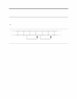
of a valid Execute Drive Diagnostics command for drive 1 to assert PDIAG-. Device 1 clears BSY before asserting PDIAG- and PDIAG- is used to indicate that Device 1 has passed its diagnostics and is ready to post status. If DASP- was not asserted by Device 1 during reset initialization, Device 0 shall post its own status immediately after it completes diagnostics and clear the Device 1 Status register to 00h. Device 0 may be unable to accept commands until it has finished its reset procedure and is ready (DRDY=1). Device 1 releases PDIAG-/CBLID- no later than after the first command following a power on or hardware reset sequence so that the host may sample PDIAG-/CBLID- in order to detect the presence or absence of an 80-conductor cable assembly. CSEL (Cable Select) (Optional) The drive is configured as either Device 0 or 1 depending upon the value of CSEL. O If CSEL is grounded the device address is 0. O If CSEL is open the device address is 1. KEY Pin position 20 has no connection pin. It is recommended to close the respective position of the cable connector in order to avoid incorrect insertion by mistake. IORDY This signal is negated to extend the host transfer cycle when a drive is not ready to respond to a data transfer request, and may be negated when the host transfer cycle is less than 240 ns for PIO data transfer. This signal is an open-drain output with 24 mA sink capability and an external resistor is needed to pull this line to +5 Volts. DMACK- This signal is used by the host in response to DMARQ to either acknowledge that data has been accepted or that data is available. This signal is internally pulled up to +5 Volts through a 15 KΩ resistor and the tolerance of the resistor value is -50% to +100%. DMARQ This signal-used for DMA data transfers between host and drive-is asserted by the drive when it is ready to transfer data to or from the host. The direction of data transfer is controlled by DIOR- and DIOW-. This signal is used to handshake with the DMACKsignal. This signal is a 3-state line with 24 mA sink capability and internally pulled down to GND through a 10 KΩ resistor. HDMARDY- (Ultra DMA) This signal is used only for Ultra DMA data transfers between the host and the device. HDMARDY- is a flow control signal for Ultra DMA data in bursts. This signal is held asserted by the host to indicate to the device that the host is ready to receive Ultra DMA data in transfers. The host may negate HDMARDY- to pause an Ultra DMA data in transfer. HSTROBE (Ultra DMA) This signal is used only for Ultra DMA data transfers between the host and the device. HSTROBE is the data out strobe signal from the host for an Ultra DMA data out transfer. Both the rising and falling edge of HSTROBE latch the data from DD00-DD15 into the device. The host may stop toggling HSTROBE to pause an Ultra DMA data out transfer. STOP (Ultra DMA) This signal is used only for Ultra DMA data transfers between the host and the device. The STOP signal is asserted by the host prior to initiation of an Ultra DMA burst. The STOP signal is negated by the host before data is transferred in an Ultra DMA burst. Assertion of STOP by the host during or after data transfer in an Ultra DMA mode signals the termination of the burst. Deskstar 60 GXP Hard disk drive specification 28
-
 1
1 -
2
-
3
-
4
-
5
-
6
-
7
-
8
-
9
-
10
-
11
-
12
-
13
-
14
-
15
-
16
-
17
-
18
-
19
-
20
-
21
-
22
-
23
-
24
-
25
-
26
-
27
-
28
-
29
-
30
-
31
-
32
-
33
-
34
-
35
-
36
-
 37
37 -
 38
38 -
 39
39 -
 40
40 -
 41
41 -
 42
42 -
 43
43 -
 44
44 -
 45
45 -
 46
46 -
 47
47 -
48
-
49
-
50
-
51
-
52
-
53
-
54
-
55
-
56
-
57
-
58
-
59
-
60
-
61
-
62
-
63
-
64
-
65
-
66
-
67
-
68
-
69
-
70
-
71
-
72
-
73
-
74
-
75
-
76
-
77
-
78
-
79
-
80
-
81
-
82
-
83
-
84
-
85
-
86
-
87
-
88
-
89
-
90
-
91
-
92
-
93
-
94
-
95
-
96
-
97
-
98
-
99
-
100
-
101
-
102
-
103
-
104
-
105
-
106
-
107
-
108
-
109
-
110
-
111
-
112
-
113
-
114
-
115
-
116
-
117
-
118
-
119
-
120
-
121
-
122
-
123
-
124
-
125
-
126
-
127
-
128
-
129
-
130
-
131
-
132
-
133
-
134
-
135
-
136
-
137
-
138
-
139
-
140
-
141
-
142
-
143
-
144
-
145
-
146
-
147
-
148
-
149
-
150
-
151
-
152
-
153
-
154
-
155
-
156
-
157
-
158
-
159
-
160
-
161
-
162
-
163
-
164
-
165
-
166
-
167
-
168
-
169
-
170
-
171
-
172
-
173
-
174
-
175
-
176
-
177
-
178
-
179
-
180
-
181
-
182
-
183
-
184
-
185
-
186
-
187
-
188
-
189
-
190
-
191
-
192
-
193
-
194
-
195
-
196
-
197
-
198
-
199
-
200
-
201
-
202
-
203
-
204
-
205
-
206
-
207
-
208
-
209
 |
 |