IBM IC35L020 Hard Drive Specifications - Page 95
S.M.A.R.T. function, 6.4 Interface capability for power modes, 7.1 Attributes, 7.2 Attribute values
 |
View all IBM IC35L020 manuals
Add to My Manuals
Save this manual to your list of manuals |
Page 95 highlights
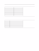
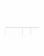
13.6.4 Interface capability for power modes Each power mode affects the physical interface as defined in the following table. Mode Active Idle Standby Sleep BSY X O O O RDY X 1 1 1 Interface active Yes Yes Yes No Media Active Active Inactive Inactive Figure 69. Power conditions Ready (RDY) is not a power condition. A device may post ready at the interface even though the media may not be accessible. 13.7 S.M.A.R.T. function The intent of Self-Monitoring Analysis and Reporting Technology (S.M.A.R.T) is to protect user data and prevent unscheduled system downtime that may be caused by predictable degradation and/or fault of the device. By monitoring and storing critical performance and calibration parameters, S.M.A.R.T devices employ sophisticated data analysis algorithms to predict the likelihood of near-term degradation or fault condition. By alerting the host system of a negative reliability status condition, the host system can warn the user of the impending risk of a data loss and advise the user of appropriate action. 13.7.1 Attributes Attributes are the specific performance or calibration parameters that are used in analyzing the status of the device. Attributes are selected by the device manufacturer based on the ability of that attribute to contribute to the prediction of degrading or faulty conditions for that particular device. The specific set of attributes being used and the identity of these attributes is vendor specific and proprietary. 13.7.2 Attribute values Attribute values are used to represent the relative reliability of individual performance or calibration attributes. The valid range of attribute values is from 1 to 253 decimal. Higher attribute values indicate that the analysis algorithms being used by the device are predicting a lower probability of a degrading or faulty condition existing. Accordingly, lower attribute values indicate that the analysis algorithms being used by the device are predicting a higher probability of a degrading or faulty condition. 13.7.3 Attribute thresholds Each attribute value has a corresponding attribute threshold limit which is used for direct comparison to the attribute value to indicate the existence of a degrading or faulty condition. The numerical values of the attribute thresholds are determined by the device manufacturer through design and reliability testing and analysis. Each attribute threshold represents the lowest limit to which its corresponding attribute value can be equal while still retaining a positive reliability status. Attribute thresholds are set at the device manufacturer's factory and cannot be changed in the field. The valid range for attribute thresholds is from 1 through 253 decimals. Deskstar 60 GXP Hard disk drive specification 81
-
 1
1 -
2
-
3
-
4
-
5
-
6
-
7
-
8
-
9
-
10
-
11
-
12
-
13
-
14
-
15
-
16
-
17
-
18
-
19
-
20
-
21
-
22
-
23
-
24
-
25
-
26
-
27
-
28
-
29
-
30
-
31
-
32
-
33
-
34
-
35
-
36
-
37
-
38
-
39
-
40
-
41
-
42
-
43
-
44
-
45
-
46
-
47
-
48
-
49
-
50
-
51
-
52
-
53
-
54
-
55
-
56
-
57
-
58
-
59
-
60
-
61
-
62
-
63
-
64
-
65
-
66
-
67
-
68
-
69
-
70
-
71
-
72
-
73
-
74
-
75
-
76
-
77
-
78
-
79
-
80
-
81
-
82
-
83
-
84
-
85
-
86
-
87
-
88
-
89
-
 90
90 -
 91
91 -
 92
92 -
 93
93 -
 94
94 -
 95
95 -
 96
96 -
 97
97 -
 98
98 -
 99
99 -
 100
100 -
101
-
102
-
103
-
104
-
105
-
106
-
107
-
108
-
109
-
110
-
111
-
112
-
113
-
114
-
115
-
116
-
117
-
118
-
119
-
120
-
121
-
122
-
123
-
124
-
125
-
126
-
127
-
128
-
129
-
130
-
131
-
132
-
133
-
134
-
135
-
136
-
137
-
138
-
139
-
140
-
141
-
142
-
143
-
144
-
145
-
146
-
147
-
148
-
149
-
150
-
151
-
152
-
153
-
154
-
155
-
156
-
157
-
158
-
159
-
160
-
161
-
162
-
163
-
164
-
165
-
166
-
167
-
168
-
169
-
170
-
171
-
172
-
173
-
174
-
175
-
176
-
177
-
178
-
179
-
180
-
181
-
182
-
183
-
184
-
185
-
186
-
187
-
188
-
189
-
190
-
191
-
192
-
193
-
194
-
195
-
196
-
197
-
198
-
199
-
200
-
201
-
202
-
203
-
204
-
205
-
206
-
207
-
208
-
209
 |
 |
