Icom IC-A110 Instruction Manual
Icom IC-A110 Manual
 |
View all Icom IC-A110 manuals
Add to My Manuals
Save this manual to your list of manuals |
Icom IC-A110 manual content summary:
- Icom IC-A110 | Instruction Manual - Page 1
INSTRUCTION MANUAL VHF AIR BAND TRANSCEIVER iA110 This device complies with Part 15 of the FCC Rules. Operation is subject to the condition that this device does not cause harmful interference. - Icom IC-A110 | Instruction Manual - Page 2
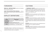
FOREWORD CAUTIONS READ ALL INSTRUCTIONS carefully and completely before using the transceiver. SAVE THIS INSTRUCTION MANUAL - This in- struction manual contains important operating instructions for the IC-A110. EXPLICIT DEFINITIONS R WARNING! NEVER operate the transceiver with a headset or other - Icom IC-A110 | Instruction Manual - Page 3
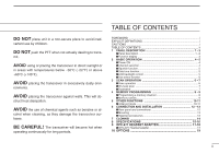
7 I Dualwatch 7 4 MEMORY PROGRAMMING 8 - 9 I Programming a memory channel 8 I Memory names 9 5 OTHER FUNCTIONS 10-11 I Initial set mode 10-11 6 CONNECTION AND INSTALLATION 12 - 13 I Rear panel and connections 12 I Mounting 13 I Supplied accessories 13 7 CLONING 14 8 SPECIFICATIONS 15-16 - Icom IC-A110 | Instruction Manual - Page 4
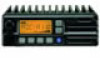
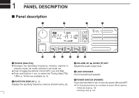
. ➥ Push to toggle the dimmer control OFF, Low and High. ➥ Push and hold for 1 sec. to select the Tuning Step [TS]; 1 MHz or 10 kHz are available. (p. 5) e VOLUME UP [Y] DOWN [Z] KEY Adjusts the audio output level. r LOUD SPEAKER Front mounted loud speaker. w FUNCTION DISPLAY (p. 3) Displays the - Icom IC-A110 | Instruction Manual - Page 5
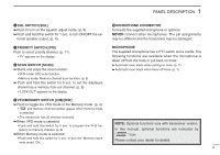
channels. ➥When VFO mode is selected; •Push and hold this switch for 5 sec. to program the VFO frequency to memory channel. (p. 8) NOTE: Optional functions vary with transceiver version. In this manual, optional functions are indicated by ➥When Memory mode is selected; • Push and hold this switch - Icom IC-A110 | Instruction Manual - Page 6
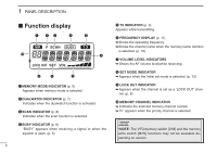
1 PANEL DESCRIPTION I Function display - Icom IC-A110 | Instruction Manual - Page 7
transceiver as indicated in the following sec- tions. e Select the desired memory channel (or VFO frequency) with the [V/M] keys. • When receiving a signal, appears and audio is emit- ted from the speaker a memory name. ï External speaker output control External speaker output can be turned OFF - Icom IC-A110 | Instruction Manual - Page 8
HEAD SET ADAPTOR, the transceiver outputs your transmitted voice to the headset for monitoring. (p. 17) I LCD backlight control The backlight of the use regular tuning (25 kHz or 8.33* kHz) when you want to change the frequency in smaller increments. *Except USA version qPush [V/M] to select - Icom IC-A110 | Instruction Manual - Page 9
scan or Priority scan is pre-programmed by cloning. Please ask your dealer or system operator for details. • VFO scan Repeatedly scans all frequencies over the entire band. Scan step is minimum channel spacing. (eg 25 kHz or 8.33* kHz) *Except USA version lowest frequency Start Scan Jump - Icom IC-A110 | Instruction Manual - Page 10
the hook to restart scanning. r Scan restarts 2 sec. after the signal disappears even if you did not converse the station. When you take the microphone during the scan operation. ➥ • In VFO scan; scan resumes promptly to frequency. ➥ • In memory scan; scan resumes promptly to memory channel. ➥ • In - Icom IC-A110 | Instruction Manual - Page 11
PROGRAMMING I Programming a memory channel D Setting lock out channels In order to speed up the scan interval, you can set memory channels you don't wish to be scanned as lock out channels. The transceiver and the memory write switch [M/W] functions may not be available depending on version. 8 - Icom IC-A110 | Instruction Manual - Page 12
. r Push [SCAN/MW] for 2 sec. to input the set name. • Flashing stops. • Memory channels can be programmed with names of up to 7 characters in length. • When no name is programmed, the display shows the operating frequency. [EXAMPLE]: Setting the name to " TOWER 2" V/M for 5 sec. + NOTE: •Push - Icom IC-A110 | Instruction Manual - Page 13
and holding [V/M] + [TS(DIAL)], push [POWER] sw to turn power ON. • The transceiver enters initial set mode and "MN", "BP", "ST" or "PR" (p. 11) appears name instead of frequency. • When a memory channel has not been programmed with a name, frequency indication appears instead. D Beep tones ON/OFF - Icom IC-A110 | Instruction Manual - Page 14
The default setting for the priority channel will differ depending on pre-programming. ➥ Push [PRI] to toggle the priority channel mode or [V/M] and [DIAL(TS)], push [POWER] to turn the power ON. • The transceiver enters initial set mode. wPush [TS(DIAL)] to select the priority channel set mode - Icom IC-A110 | Instruction Manual - Page 15
› External speaker jack ⁄ Antenna ¤ fi OPC-871 HEADSET ADAPTER (Option) ‹ Supplied DC power cable black: . red: , 12 V or 24 V Battery q Connects to an antenna Ask your dealer about antenna selection and best installation location. (Standard 50 Ω antenna with a SWR - Icom IC-A110 | Instruction Manual - Page 16
mm thick and can support more than 5 kg. • Mount the transceiver so that the face of the transceiver is at 90 ˚ to your line of sight when operating. 5 6 7 8 9 0 A B q Microphone 1. w Microphone hanger and screw set 1 set e Microphone cable 1 r DC power cable (OPC-344 1 t Mounting bracket - Icom IC-A110 | Instruction Manual - Page 17
programmed contents from one transceiver to another transceiver, or, data from PC to a transceiver using the optional CS-A110 cloning software. D Cloning using PC Data can be cloned to and from a PC (IBM compatible) using the optional CS-A110 CLONING SOFTWARE and the optional OPC478 CLONING CABLE - Icom IC-A110 | Instruction Manual - Page 18
: More than 25 dB • Modulation limiting : 70 to 100 % • Audio output impedance : Ext. SP 8 Ω • Audio harmonic distortion : Less than 10 % Side tone 500 Ω (at 85 % modulation) • Hum and noise ratio : More than 40 dB *Except USA version • Spurious emissions • Antenna impedance : -16dBm - Icom IC-A110 | Instruction Manual - Page 19
.065 118.080 118.085 118.090 118.105 8 SPECIFICATIONS (VFO CHANNEL ID LIST) • Channel spacing: 25/8.33* kHz auto selection mode Operating Freq. Channel spacing (MHz) (kHz) 118.0000 25 118.0000 8.33 118.0083 8.33 118.0167 8.33 118.0250 25 118.0250 8.33 118.0333 8.33 118.0417 8.33 - Icom IC-A110 | Instruction Manual - Page 20
headset, such as those from the David Clark Co. via the adapter, the transceiver outputs your transmitted voice to the headset for monitoring. (pgs. 5, 10) install as follows. q Turns the power OFF, then disconnect the DC power cable. wUnscrew the 4 screws, then remove the bottom cover. (Fig. 1) e - Icom IC-A110 | Instruction Manual - Page 21
• Use the upper side mounting hole. • You can mount the attachment on either side of the transceiver. • Bent the plastic dust cover before install the strain relief into the notch. Fig. 2 OPC-871 9 Fig. 3 18 - Icom IC-A110 | Instruction Manual - Page 22
ADAPTER (See pgs. 17-18) CS-A110 CLONING SOFTWARE Provides quick and easy programming of items, including private channels, scan settings, etc., via an IBM® compatible PC (Microsoft® Windows® 95/98) to transceiver. OPC-478 CLONING CABLE OPC-592 CLONING CABLE ADAPTOR These three components work as - Icom IC-A110 | Instruction Manual - Page 23
- Icom IC-A110 | Instruction Manual - Page 24
A-5616H-1EX-q Printed in Japan © 1999 Icom Inc. 1-1-32 Kamiminami, Hirano-ku, Osaka 547-0003 Japan
-
 1
1 -
 2
2 -
 3
3 -
 4
4 -
 5
5 -
 6
6 -
 7
7 -
8
-
9
-
10
-
11
-
12
-
13
-
14
-
15
-
16
-
17
-
18
-
19
-
20
-
21
-
22
-
23
-
24
 |
 |

iA110
VHF AIR BAND TRANSCEIVER
INSTRUCTION MANUAL
This device complies with Part 15 of the
FCC Rules. Operation is subject to the
condition that this device does not cause
harmful interference.