Icom IC-A110 Instruction Manual - Page 5
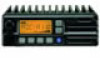
Sql Switch [sql], Priority Switch [pri], Scan Switch [scan], Microphone Connector, Never, Microphone - external speaker
 |
View all Icom IC-A110 manuals
Add to My Manuals
Save this manual to your list of manuals |
Page 5 highlights
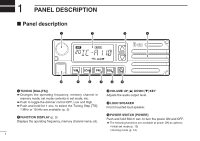
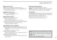
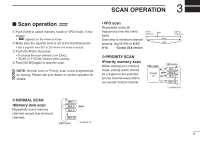
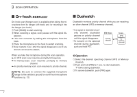
PANEL DESCRIPTION 1 y SQL SWITCH [SQL] ➥ Push to turn on the squelch adjust mode. (p. 6) ➥ Push and hold this switch for 1 sec. to turn ON/OFF the ex- ternal speaker output. (p. 4) !0 MICROPHONE CONNECTOR Connects the supplied microphone or optional. NEVER connect other microphones. The pin assignments may be different and the transceiver may be damaged. u PRIORITY SWITCH [PRI] Push to select priority channel. (p. 11) • "Pr" appears on the display. i SCAN SWITCH [SCAN] ➥ Starts and stops the scan function: • VFO mode: VFO scan function. • Memory mode: Memory channel scan function. (p. 6) ➥ Push and hold this switch for 5 sec. to set the displayed channel as a memory lock-out channel. (p. 8) • "LOCK OUT" appears on the display. MICROPHONE The supplied microphone has a PTT switch and a cradle. The following functions are available when the microphone is taken off from the hook or put back on hook: ➥ Automatic scan starts when putting on hook. (p. 7) ➥ Automatic scan stops when taken off hook. (p. 7) o VFO/MEMORY SWITCH [V/M]/[MW] ➥ Push to toggle the VFO mode or the Memory mode. (p. 4) • "X" and memory channel number appear when memory mode is selected. • The transceiver has 20 memory channels. ➥When VFO mode is selected; •Push and hold this switch for 5 sec. to program the VFO frequency to memory channel. (p. 8) NOTE: Optional functions vary with transceiver version. In this manual, optional functions are indicated by ➥When Memory mode is selected; • Push and hold this switch for 5 sec. to turn the "Memory name write mode" ON. " " Icon. Please contact your dealer for details. 2
-
 1
1 -
 2
2 -
 3
3 -
 4
4 -
 5
5 -
 6
6 -
 7
7 -
 8
8 -
 9
9 -
 10
10 -
 11
11 -
12
-
13
-
14
-
15
-
16
-
17
-
18
-
19
-
20
-
21
-
22
-
23
-
24
 |
 |
