Image Fitness 4.5 Bench English Manual - Page 10
Note: Position
 |
View all Image Fitness 4.5 Bench manuals
Add to My Manuals
Save this manual to your list of manuals |
Page 10 highlights
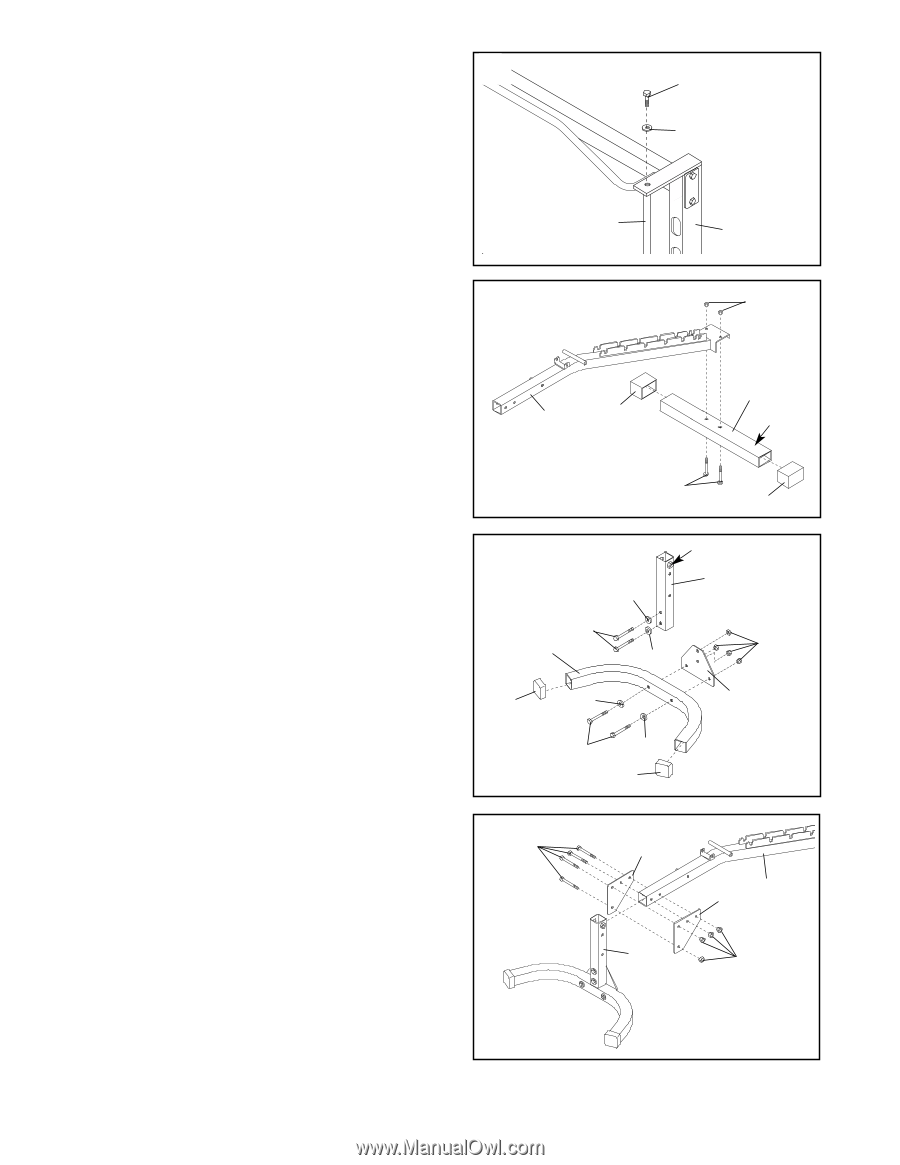
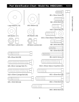
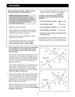
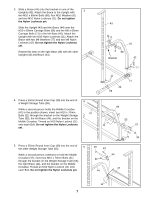
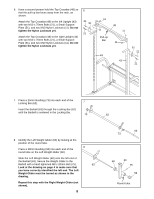
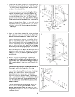
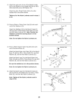
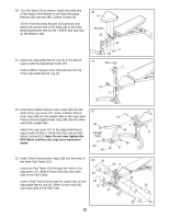
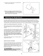
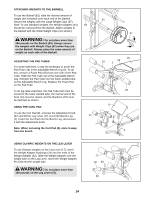
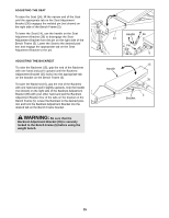
12. Attach the upper end of one of the Weight Guides (53) to the bracket on the Upright (43) with an M8 x 12 30mm Bolt (64) and an M8 Washer (77). Attach the other Weight Guide (53) to the other Upright (43) in the same manner. Tighten all of the Nylon Locknuts used in steps 1 to 12. 64 77 53 43 13. Press a 50mm x 70mm Outer Cap (10) onto each 13 end of the Stabilizer (13). Attach the Stabilizer (13) to the Bench Frame (5) with two M10 x 60mm Button Head Bolts (12) and two M10 Nylon Locknuts (11). Note: Position the Stabilizer so that the warning decal is in the position shown. Note: Do not tighten the Nylon Locknuts yet. 5 10 11 13 Decal 12 10 14. Press a 50mm Square Outer Cap (20) onto each end of the Bench Base (7). Attach the Bench Base Joint Plate (19) to the Bench Base (7) with two M10 x 70mm Bolts (21), two M10 Washers (6), and two M10 Nylon Locknuts (11). Attach the Bench Leg (1) to the Bench Base Joint Plate (19) with two M10 x 70mm Bolts (21), two M10 Washers (6), and two M10 Nylon Locknuts (11). Be sure the welded nut is in the position shown. Note: Do not tighten the Nylon Locknuts yet. 14 20 21 7 6 6 6 21 6 20 Welded Nut 1 11 19 15. Attach the Bench Leg (1) to the Bench Frame (5) with two Bench Joint Plates (18), four M10 x 70mm Bolts (21), and four M10 Nylon Locknuts (11). Note: Tighten all the Nylon Locknuts used in steps 13-15. 15 21 18 5 18 1 11 10
-
 1
1 -
2
-
3
-
4
-
 5
5 -
 6
6 -
 7
7 -
 8
8 -
 9
9 -
 10
10 -
 11
11 -
 12
12 -
 13
13 -
 14
14 -
 15
15 -
16
-
17
-
18
-
19
 |
 |