Intel A2400SATAKIT Installation Guide - Page 14
Install the SATA Cable(s)
 |
View all Intel A2400SATAKIT manuals
Add to My Manuals
Save this manual to your list of manuals |
Page 14 highlights
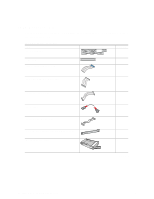
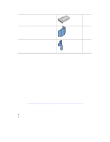
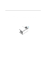
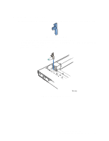
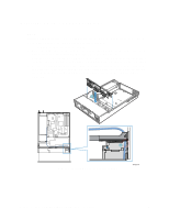
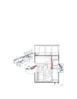
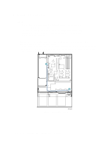
Install the SATA Cable(s) ✏ NOTE Disregard this step if you installed the SCSI backplane and instead follow the steps for Install the SCSI Cable. 1. Connect the SATA Cable(s) labeled SATA CH A and SATA CH B to the backplane. See letter "A" in the figure below to locate the backplane. See letter "B" in the figure to identify the end of the SATA cable that is attached to the backplane. 2. If you will be using the SATA connections on the server board instead of an an add-in SATA RAID Controller, connect the 90-degree end of the SATA cable(s) to the corresponding server board connection(s). The cable connected to SATA CH A should be connected to SATA 0. The cable connected to SATA CH B should be connected to SATA 1. See letter "C" in the figure below to identify the end of the SATA cable that is attached to the server board. See your server board documentation to locate the SATA connection points on the server board. If you will be using an add-in SATA RAID Controller, you will need to connect SATA CH A through SATA CH E to the appropriate connectors on the add-in card after you install the addin card. See your add-in card documentation for the appropriate SATA connections. SATA SATA CH A SATA CH B SATA CH D CH C A A SATA CH E B SATA1 SATA0 C Figure 5. Installing SATA Cables to Server Board TP01078 8 Intel® Server Chassis SR2400 SCSI and SATA Backplane Installation Instructions
-
 1
1 -
2
-
3
-
4
-
5
-
6
-
7
-
8
-
 9
9 -
 10
10 -
 11
11 -
 12
12 -
 13
13 -
 14
14 -
 15
15 -
 16
16 -
 17
17 -
 18
18 -
 19
19 -
20
-
21
-
22
-
23
-
24
-
25
 |
 |
