Intel D525MW Product Specification
Intel D525MW Manual
 |
View all Intel D525MW manuals
Add to My Manuals
Save this manual to your list of manuals |
Intel D525MW manual content summary:
- Intel D525MW | Product Specification - Page 1
Board D525MW and Intel Desktop Board D525MWV may contain design defects or errors known as errata that may cause the product to deviate from published specifications. Current characterized errata are documented in the Intel Desktop Board D525MW and Intel Desktop Board D525MWV Specification Update. - Intel D525MW | Product Specification - Page 2
This product specification applies to only the standard Intel® Desktop Board D525MW and Intel® Desktop Board D525MWV with BIOS identifier MWPNT10N.86A. Changes to this specification will be published in the Intel Desktop Board D525MW and Intel Desktop Board D525MWV Specification Update before being - Intel D525MW | Product Specification - Page 3
Specification (TPS) specifies the board layout, components, connectors, power and environmental requirements, and the BIOS for the Intel® Desktop Board D525MW and Intel® Desktop Board D525MWV the board The features supported by the BIOS Setup program A description of the BIOS error messages, beep - Intel D525MW | Product Specification - Page 4
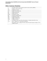
Desktop Board D525MW and Intel Desktop Board D525MWV Technical Product Specification Other Common Notation # GB GB/s Gbit KB Kbit 073,741,824 bits) Kilobyte (1024 bytes) Kilobit (1024 bits) 1000 bits per second Megabyte (1,048,576 bytes) Megabytes per second Megabit (1,048,576 bits) Megabits per - Intel D525MW | Product Specification - Page 5
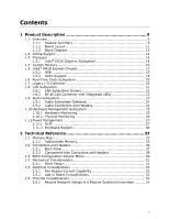
14 1.3.1 Intel® D525 Graphics Subsystem ...15 1.4 System Memory ...16 1.5 Intel® NM10 Express Chipset...17 1.5.2 USB ...19 1.5.3 SATA Support ...19 1.6 Real-Time Clock Subsystem ...20 1.7 Legacy I/O Controller ...20 1.8 LAN Subsystem ...21 1.8.1 LAN Subsystem Drivers ...21 1.8.2 RJ-45 LAN Connector - Intel D525MW | Product Specification - Page 6
Intel Desktop Board D525MW and Intel Desktop Board D525MWV Technical Product Specification 2.7 Power Consumption ...2.7.1 Minimum Load Configuration...2.7.2 Maximum Load Configuration ...2.8 Reliability ...2.9 Environmental ...3.1 Introduction ...3.2 BIOS Flash Memory Organization ...3.3 Resource - Intel D525MW | Product Specification - Page 7
...12 Supported Memory Configurations ...16 LAN Connector LED States ...22 Audio Jack Support ...23 Effects of Pressing the Power Switch ...27 Power States and Targeted System Power...28 Wake-up Devices and Events ...29 System Memory Map ...35 Component-side Connectors and Headers Shown in Figure 10 - Intel D525MW | Product Specification - Page 8
Desktop Board D525MW and Intel Desktop Board D525MWV Technical Product Specification 23. 24. 25. 26. 27. 28. 29. 30. 31. 32. 33. 34. 35. 36. 37. 38. 39. 40. 41. 42. 43. 44. 45. 46. Power Connector ...Front Panel Header ...States for a One-Color Power LED ...BIOS Configuration Jumper Settings...Fan - Intel D525MW | Product Specification - Page 9
Desktop Board D525MW and Intel Desktop Board D525MWV. Table 1. Feature Summary Form Factor Processor Memory Mini-ITX, (6.7 inches by 6.7 inches [170 millimeters by 170 millimeters]) compatible with microATX Passively-cooled, soldered-down Dual-Core Intel® Atom™ processor with integrated graphics and - Intel D525MW | Product Specification - Page 10
Subsystem • Support for PCI* Local Bus Specification Revision 2.3 • Suspend to RAM support • Wake on PCI, PCI Express*, PS/2, serial, front panel, USB ports, and LAN • One PCI Conventional bus connector (with riser card support for up to two PCI cards) • PCI Express x1 Mini Card connector • Hardware - Intel D525MW | Product Specification - Page 11
Product Description 1.1.2 Board Layout Figure 1 shows the location of the major components. Figure 1. Major Board Components Table 2 lists the components identified in Figure 1. 11 - Intel D525MW | Product Specification - Page 12
1 SATA connector 0 Front panel USB header (black) Front panel header Standby power LED BIOS setup configuration jumper block PCI Express x1 Mini Card connector Intel NM10 Express Chipset Front Panel Wireless Activity LED Header Front panel USB header supports Intel Z-U130 USB Solid-State Drive or - Intel D525MW | Product Specification - Page 13
Product Description 1.1.3 Block Diagram Figure 2 is a block diagram of the major functional areas. Figure 2. Block Diagram 13 - Intel D525MW | Product Specification - Page 14
/chipsets/index.htm http://downloadcenter.intel.com http://www.intel.com/support/motherboards/desktop/sb/CS025414.htm http://www.intel.com/support/go/buildit 1.3 Processor The board has a passively-cooled, soldered-down Dual-Core Intel Atom processor with integrated graphics and integrated memory - Intel D525MW | Product Specification - Page 15
Pixel Shader 2.0 • ⎯ Vertex Shader Model 2.0 3D Graphics Rendering enhancements ⎯ 1.6 dual texture GigaPixel/s max fill rate ⎯ 16-bit and 32-bit color • ⎯ Vertex cache Video ⎯ Software DVD at 30 fps full screen • ⎯ DVMT support up to 256 MB Display ⎯ Supports analog displays up to 2048 x 1536 at 75 - Intel D525MW | Product Specification - Page 16
compliant with all applicable DDR3 SDRAM memory specifications, the board should be populated with DIMMs that support the Serial Presence Detect (SPD) data structure. This allows the BIOS to read the SPD data and program the chipset to accurately configure memory settings for optimum performance. If - Intel D525MW | Product Specification - Page 17
The Intel NM10 Express chipset Resources used by the chipset Refer to http://www.intel.com/products/desktop/chipsets/index.htm Chapter 2 1.5.1.1 Video Memory Allocation Video memory is allocated from the total available system memory for the efficient balancing of 2-D/3-D graphics performance - Intel D525MW | Product Specification - Page 18
D525MW and Intel Desktop Board D525MWV Technical Product Specification 1.5.1.4 Configuration Modes For monitors attached to the VGA port, video modes supported by this board are based on the Extended Display Identification Data (EDID) protocol. Video mode configuration for LVDS displays (D525MWV - Intel D525MW | Product Specification - Page 19
UHCI and EHCI, and uses UHCI- and EHCI-compatible drivers (four ports routed to the back panel and three ports routed to two front panel USB 2.0 headers). One of the front panel USB headers (brown-colored) supports an Intel Z-U130 USB Solid-State Drive or compatible device. NOTE Computer systems - Intel D525MW | Product Specification - Page 20
wake-up event interface PCI Conventional bus power management support The Legacy I/O Controller provides the following features: The BIOS Setup program provides configuration options for the Legacy I/O controller. For information about The location of the serial port header The serial port header - Intel D525MW | Product Specification - Page 21
1.8 LAN Subsystem Intel NM10 Express Chipset Realtek 8111E Gigabit Ethernet Controller for 10/100/1000 Mbit/s Ethernet LAN connectivity RJ-45 LAN connector with integrated status LEDs CSMA/CD protocol engine LAN connect interface that supports the Ethernet controller PCI Conventional bus power - Intel D525MW | Product Specification - Page 22
Intel Desktop Board D525MWV Technical Product Specification 1.8.2 RJ-45 LAN Connector with Integrated LEDs Two LEDs are built into the RJ-45 LAN connector (shown in Figure 3). Figure 3. LAN Connector LED Locations Table 4 describes the LED states when the board is powered up and the Ethernet LAN - Intel D525MW | Product Specification - Page 23
• • • Audio Subsystem Intel NM10 Express Chipset Realtek ALC662 audio codec Advanced jack sense Intel HD Audio and AC '97 audio support 3-port analog audio out stack Windows Vista Basic certification A signal-to-noise (S/N) ratio of 95 dB The board supports the Intel® High Definition Audio (Intel - Intel D525MW | Product Specification - Page 24
Intel Desktop Board D525MW and Intel Desktop Board D525MWV Technical Product Specification 1.9.1 Audio Subsystem Software Refer to Section 1.2, page 14 Audio software and drivers are available from Intel's World Wide Web site. For information about Obtaining audio software and drivers 1.9.2 - Intel D525MW | Product Specification - Page 25
monitoring Chassis intrusion detection 1.10.1 Hardware Monitoring The hardware monitoring and fan control subsystem is based on the Winbond W83627DHG-A device, which supports the following: Processor and system ambient temperature monitoring Chassis fan speed monitoring Power monitoring of +12 - Intel D525MW | Product Specification - Page 26
Desktop Board D525MW and Intel Desktop Board D525MWV Technical Product Specification 1.10.2 Thermal Monitoring Figure 5 shows the locations of the thermal sensors and fan header. Item A B C Description Chassis fan header Remote thermal sensor Thermal diode, located on the processor die Figure - Intel D525MW | Product Specification - Page 27
Advanced Configuration and Power Interface (ACPI) Hardware support: ⎯ Power connector ⎯ Fan header ⎯ LAN wake capabilities ⎯ Instantly Available PC technology ⎯ Wake from USB ⎯ Wake from PS/2 devices ⎯ Power Management Event signal (PME#) wake-up support ⎯ WAKE# signal wake-up support 1.11.1 ACPI - Intel D525MW | Product Specification - Page 28
computer. Notes: 1. 2. No power No power to the system. Service can be performed safely. Total system power is dependent on the system configuration, including add-in boards and peripherals powered by the system's power supply. Dependent on the standby power consumption of wake-up devices used in - Intel D525MW | Product Specification - Page 29
specific states. Table 8. Wake-up Devices and Events These devices/events can wake up the computer...LAN PME# signal Wake# signal Power switch RTC alarm Serial port USB PS/2 devices Notes: 1. 2. 3. 4. S4 implies operating system support only. Wake from S5 must include wake after loss of power. USB - Intel D525MW | Product Specification - Page 30
Desktop Board D525MW and Intel Desktop Board D525MWV Technical Product Specification 1.11.2 Hardware Support The board provides several power management hardware features, including: Power connector Fan header LAN wake capabilities Instantly Available PC technology Wake from USB Wake from PS - Intel D525MW | Product Specification - Page 31
that also support this specification can participate in power management and can be used to wake the computer. The use of Instantly Available PC technology requires operating system support and PCI 2.3 compliant add-in cards and drivers. 1.11.2.4 Wake from USB USB bus activity wakes the computer - Intel D525MW | Product Specification - Page 32
Intel Desktop Board D525MW and Intel Desktop Board D525MWV Technical Product Specification 1.11.2.9 +5 V Standby Power Indicator LED The +5 V standby power indicator LED shows that power is still present even when the computer appears to be off. Figure 6 shows the location of the standby power - Intel D525MW | Product Specification - Page 33
. Typically the address space that is allocated for PCI Conventional bus add-in cards, PCI Express configuration space, BIOS (SPI Flash), and chipset overhead resides above the top of DRAM (total system memory). On a system that has 4 GB of system memory installed, it is not possible to use all - Intel D525MW | Product Specification - Page 34
Intel Desktop Board D525MW and Intel Desktop Board D525MWV Technical Product Specification The amount of installed memory that can be used will vary based on add-in cards and BIOS settings. Figure 7 shows a schematic of the system memory map. All installed system memory can be used when there is no - Intel D525MW | Product Specification - Page 35
4095 MB 64 KB 64 KB 96 KB Description Extended memory Runtime BIOS Reserved Potential available high DOS memory (open to the PCI bus). Dependent on video adapter used. Video memory and BIOS Extended BIOS data (movable by memory manager software) Extended conventional memory Conventional memory 640 - Intel D525MW | Product Specification - Page 36
Intel Desktop Board D525MW and Intel Desktop Board D525MWV Technical Product Specification 2.2 Connectors and Headers CAUTION Only the following connectors/headers have overcurrent protection: Back panel and front panel USB, VGA, serial, and PS/2. The other internal connectors/headers are not - Intel D525MW | Product Specification - Page 37
the location of the back panel connectors. Item A B C D E F G H I J K Description PS/2 keyboard/mouse PS/2 keyboard/mouse Serial port Parallel port VGA port USB ports LAN USB ports Line in Line out Mic in Figure 8. Back Panel Connectors NOTE The back panel audio line out connector is designed to - Intel D525MW | Product Specification - Page 38
Board D525MWV Technical Product Specification 2.2.1.2 I/O Shield The I/O shield provided with the board allows access to all back panel connectors and is compatible with standard mini-ITX and microATX chassis. As an added benefit for system configurations with wireless PCI Express Mini Card - Intel D525MW | Product Specification - Page 39
Technical Reference 2.2.2 Component-side Connectors and Headers Figure 10 shows the locations of the component-side connectors and headers. Figure 10. Component-side Connectors and Headers 39 - Intel D525MW | Product Specification - Page 40
connector (D525MWV only) Processor core power connector (2 x 2) Power connector (2 x 12) SATA connector 1 SATA connector 0 USB front panel header Front panel header PCI Express x1 Mini Card connector Front Panel Wireless Activity LED Header Front panel USB header supports Intel Z-U130 USB Solid - Intel D525MW | Product Specification - Page 41
Clear To Send) Key (no pin) Table 12. LVDS Data Connector - 30-Pin (D525MWV only) Pin 1 Signal Name LA_CLKN Description LVDS Channel A diff clock output negative LVDS Channel A diff clock output positive Power for EDID ROM LVDS Channel A diff data output - negative LVDS Channel A diff data output - Intel D525MW | Product Specification - Page 42
Desktop Board D525MW and Intel Desktop Board D525MWV Technical Product Specification Table 13. LVDS Panel Voltage Selection Jumper (D525MWV only) Voltage 3.3 V Jumper Setting 2 and 4 Configuration Jumper position for 3.3 V (default) 5V 6 and 4 Jumper position for 5 V 12 V 3 and 4 Jumper - Intel D525MW | Product Specification - Page 43
7 Signal Name Ground TXP TXN Ground RXN RXP Ground Table 18. Front Panel Wireless Activity LED Header Pin 1 2 Signal Name LED (+) Ground Table 19. Front Panel Audio Header for Intel HD Audio Pin 1 3 5 7 9 Signal Name [Port 1] Left channel [Port 1] Right channel [Port 2] Right channel SENSE_SEND - Intel D525MW | Product Specification - Page 44
Intel Desktop Board D525MW and Intel Desktop Board D525MWV Technical Product Specification Table 21. Front Panel USB Header Pin 1 3 5 7 9 Signal Name +5 VDC DD+ Ground KEY (no pin) Pin 2 4 6 8 10 Signal Name +5 VDC DD+ Ground No Connect Table 22. Front Panel USB Header with Intel Z-U130 USB - Intel D525MW | Product Specification - Page 45
The board has the following add-in card connectors: PCI Express x1 Mini Card (rev 1.2 compliant) connector PCI Conventional (rev 2.3 compliant) bus connector (with riser card support for up to two PCI cards) The PCI Conventional bus connector is bus master capable. SMBus signals are routed - Intel D525MW | Product Specification - Page 46
Board D525MW and Intel Desktop Board D525MWV Technical Product Specification 2.2.2.4 Front Panel Header This section describes the functions of the front panel header. Table 24 lists the signal names of the front panel header. Figure 11 is a connection diagram for the front panel header. Table - Intel D525MW | Product Specification - Page 47
/S1) NOTE The LED states listed in Table 25 are default settings that can be modified through BIOS setup. Systems built with a dual-color front panel power LED can also use alternate color state options. 2.2.2.4.4 Power Switch Header Pins 6 and 8 can be connected to a front panel momentary-contact - Intel D525MW | Product Specification - Page 48
Desktop Board D525MW and Intel Desktop Board D525MWV Technical Product Specification 2.2.2.5 Front Panel USB Headers Figure 12 and Figure 13 are connection diagrams for the front panel USB headers. NOTE • • The +5 VDC power on the USB headers is fused. Use only a front panel USB connector that - Intel D525MW | Product Specification - Page 49
not move the jumper with the power on. Always turn off the power and unplug the power cord from the computer before changing a jumper setting. Otherwise, the board could be damaged. Figure 14 shows the location of the jumper block. The jumper determines the BIOS Setup program's mode. Table 26 lists - Intel D525MW | Product Specification - Page 50
Desktop Board D525MW and Intel Desktop Board D525MWV Technical Product Specification Table 26. BIOS Configuration Jumper Settings Function/Mode Normal Jumper Setting 1-2 Configuration The BIOS uses current configuration information and passwords for booting. Configure 2-3 After the POST runs - Intel D525MW | Product Specification - Page 51
2.4.1 Mechanical Considerations Form Factor The board is designed to fit into a mini-ITX or microATX form-factor chassis. Figure 15 illustrates the mechanical form factor for the I/O connectors and mounting holes are in compliance with the microATX specification. Figure 15. Board Dimensions 51 - Intel D525MW | Product Specification - Page 52
Desktop Board D525MW and Intel Desktop Board D525MWV Technical Product Specification 2.5 2.5.1 Electrical Considerations Fan Header Current Capability Table 27 lists the current capability of the fan header. Table 27. Fan Header Current Capability Fan Header Chassis fan Maximum Available Current - Intel D525MW | Product Specification - Page 53
proper airflow is maintained in the processor voltage regulator circuit. Failure to do so may result in damage to the voltage regulator regulator area Intel Atom processor Intel NM10 Express Chipset Figure 16. Localized High Temperature Zones Table 28 provides maximum case temperatures for the - Intel D525MW | Product Specification - Page 54
Desktop Board D525MW and Intel Desktop Board D525MWV Technical Product Specification Table 28. Thermal Considerations for Components Component Intel Atom processor Processor voltage regulator area Intel NM10 Express Chipset Memory SO-DIMM Maximum Case Temperature 99 oC 85 oC 113 oC 85 oC For - Intel D525MW | Product Specification - Page 55
Reference 2.6.1.2 Terms TA TJ ΨJA TIM TDP TA external Thermal Specifications Guideline Requirements ≤ 50 °C ≤ 100 °C ≤ 3.85 °C/W of processor power in most of the passively enabled system chassis. This board is targeted for 3-7 liters volumetric or larger, desktop/tower orientation, mini-ITX and - Intel D525MW | Product Specification - Page 56
Desktop Board D525MW and Intel Desktop Board D525MWV Technical Product Specification Figure 17. Fan Location Guide for Chassis Selection (Chassis Orientation is Not Restricted) For all chassis configurations, the heatsink performance parameter, ΨJA should be less than 3.85 °C/W. The detail thermal - Intel D525MW | Product Specification - Page 57
Windows Vista Home Basic ⎯ Load: continuous read/write benchmark 2.5-inch SATA hard disk drive ⎯ Load: continuous read/write benchmark Intel Z-U130 USB Solid-State Drive or compatible device on the USB flash drive header ⎯ Load: continuous read/write benchmark Wireless card on PCI Express x1 Mini - Intel D525MW | Product Specification - Page 58
Intel Desktop Board D525MWV Technical Product Specification USB keyboard and mouse Back and front panel host-powered USB devices (other than keyboard and mouse) ⎯ Load: continuous read/write activity on external drive/peripheral LAN linked at 1000 Mb/s ⎯ Load: continuous read/write benchmark - Intel D525MW | Product Specification - Page 59
uses an Intel BIOS that is stored in the Serial Peripheral Interface Flash Memory (SPI Flash) and can be updated using a disk-based program. The SPI Flash contains the BIOS Setup program, POST, the PCI auto-configuration utility, LAN EEPROM information, and Plug and Play support. The BIOS displays - Intel D525MW | Product Specification - Page 60
Desktop Board D525MW and Intel Desktop Board D525MWV Technical Product Specification Table 32 lists the BIOS Setup program menu features. Table 32. BIOS Setup Program Menu Bar Maintenance Clears passwords and displays processor information Main Displays processor and memory configuration Advanced - Intel D525MW | Product Specification - Page 61
interface for such operating systems. Using this support, an SMBIOS service-level application running on a non-Plug and Play operating system can obtain the SMBIOS information. Additional board information can be found in the BIOS under the Additional Information header under the Main BIOS page. 61 - Intel D525MW | Product Specification - Page 62
Desktop Board D525MW and Intel Desktop Board D525MWV Technical Product Specification 3.5 Legacy USB Support Legacy USB support enables USB devices to be used even when the operating system's USB drivers are not yet available. Legacy USB support is used to access the BIOS Setup program, and to - Intel D525MW | Product Specification - Page 63
Intel® Express BIOS Update utility, which enables automated updating while in the Windows environment. Using this utility, the BIOS can be updated from a file on a hard disk, a USB drive (a flash drive or a USB drive), or an optical drive. Intel® Flash Memory Update Utility, which requires booting - Intel D525MW | Product Specification - Page 64
and the network fourth. 3.7.1 Optical Drive Boot Booting from the optical drive is supported in compliance to the El Torito bootable CD-ROM format specification. Under the Boot menu in the BIOS Setup program, the optical drive is listed as a boot device. Boot devices are defined in priority order - Intel D525MW | Product Specification - Page 65
are not present Video adapter Keyboard Mouse 3.7.4 Changing the Default Boot Device During POST Pressing the key during POST causes a boot device menu to be displayed. This menu displays the list of available boot devices (as set in the BIOS setup program's Boot Device Priority submenu - Intel D525MW | Product Specification - Page 66
Intel Desktop Board D525MW and Intel Desktop Board D525MWV Technical Product Specification 3.8 BIOS Security Features The BIOS includes security features that restrict access to the BIOS Setup program and who can boot the computer. A supervisor password and a user password can be set for the BIOS - Intel D525MW | Product Specification - Page 67
line out audio jack (see Figure 4, B on page 24). Table 37. BIOS Beep Codes Type Pattern Frequency 932 Hz F2 Setup/F10 Boot Menu One 0.5 second beep when BIOS is ready to Prompt accept keyboard input BIOS update in progress Video error None On-off (1.0 second each) two times, then 2.5-second pause - Intel D525MW | Product Specification - Page 68
Desktop Board D525MW and Intel Desktop Board D525MWV Technical Product Specification 4.2 Front-panel Power LED Blink Codes Whenever a recoverable error occurs during POST, the BIOS causes the board's front panel power LED to blink an error message describing the problem (see Table 38). Table - Intel D525MW | Product Specification - Page 69
codes: Can be used by any PEIM/driver for debug. Host Processors: 1F is an unrecoverable CPU error. Memory/Chipset: 2F is no memory detected or no useful memory detected. Recovery: 3F indicated recovery failure. Reserved for future use. I/O Busses: PCI, USB, ISA, ATA, etc. 5F is an unrecoverable - Intel D525MW | Product Specification - Page 70
Desktop Board D525MW and Intel Desktop Board D525MWV Technical Product Specification Table 41. Port 80h POST Codes POST Code 10 11 12 13 Description of POST Operation Host Processor Power-on initialization of the host processor (Boot Strap Processor) Host processor cache initialization (including - Intel D525MW | Product Specification - Page 71
Dy Trying boot selection y (y=0 to 15) PEI Core E0 E2 E1, E3 Started dispatching PEIMs (emitted on first report of EFI_SW_PC_INIT_BEGIN EFI_SW_PEI_PC_HANDOFF_TO_NEXT) Permanent memory found Reserved for PEI/PEIMs DXE Core E4 E5 E6 Entered DXE phase Started dispatching drivers Started connecting - Intel D525MW | Product Specification - Page 72
Board D525MW and Intel Desktop Board D525MWV Technical Product Specification Table 41. Port 80h POST Codes (continued) POST Code E7 E8 E9 EB Description of POST Operation DXE Drivers Waiting for user input Checking password Entering BIOS setup Calling Legacy Option ROMs Runtime Phase/EFI OS Boot - Intel D525MW | Product Specification - Page 73
chipset component Reading SPD from memory DIMMs Detecting presence of memory DIMMs Configuring memory Testing memory PCI busses Allocating resourced to PCI bus Detecting the presence of the keyboard Resetting keyboard Clearing keyboard input buffer Keyboard Self Test Calling Video BIOS Resetting USB - Intel D525MW | Product Specification - Page 74
Intel Desktop Board D525MW and Intel Desktop Board D525MWV Technical Product Specification 74 - Intel D525MW | Product Specification - Page 75
markings 5.1 This section contains the following regulatory compliance information for Intel Desktop Board D525MW and Intel Desktop Board D525MWV: 5.1.1 Safety Standards Intel Desktop Board D525MW and Intel Desktop Board D525MWV comply with the safety standards stated in Table 43 when - Intel D525MW | Product Specification - Page 76
Desktop Board D525MW and Intel Desktop Board D525MWV Technical Product Specification 5.1.2 European Union Declaration of Conformity Statement We, Intel Corporation, declare under our sole responsibility that the product Intel® Desktop Board D525MW is in conformity with all applicable essential - Intel D525MW | Product Specification - Page 77
of this program, including the scope of covered products, available locations, shipping instructions, terms and conditions, etc Intel Product Recycling Program http://www.intel.com/intel/other/ehs/product_ecology Deutsch Als Teil von Intels Engagement für den Umweltschutz hat das Unternehmen das - Intel D525MW | Product Specification - Page 78
Intel Desktop Board D525MW and Intel Desktop Board D525MWV Technical Product Specification Español Como parte de su compromiso de responsabilidad medioambiental, Intel ha implantado el programa de reciclaje de productos Intel, que permite que los consumidores al detalle de los productos Intel - Intel D525MW | Product Specification - Page 79
tlar ve şartlar v.s dahil bütün ayrıntılarını ögrenmek için lütfen http://www.intel.com/intel/other/ehs/product_ecology Web sayfasına gidin. 5.1.4 EMC Regulations Intel Desktop Board D525MW and Intel Desktop Board D525MWV comply with the EMC regulations stated in Table 44 when correctly installed - Intel D525MW | Product Specification - Page 80
Desktop Board D525MW and Intel Desktop Board D525MWV Technical Product Specification FCC Declaration of Conformity This device complies frequency energy and, if not installed and used in accordance with the instructions, may cause harmful interference to radio communications. However, there is no - Intel D525MW | Product Specification - Page 81
or television receiver in a domestic environment, it may cause radio interference. Install and use the equipment according to the instruction manual. Korea Class B Statement Korea Class B Statement translation: This equipment is for home use, and has acquired electromagnetic conformity registration - Intel D525MW | Product Specification - Page 82
Intel Desktop Board D525MW and Intel Desktop Board D525MWV meet the ENERGY STAR requirements listed in Table 45 when used in corresponding system configurations. Table 45. ENERGY STAR Requirements Typical Electricity Consumption (TEC) Criteria N/A ENERGY STAR Specification without Wake On LAN (Sleep - Intel D525MW | Product Specification - Page 83
Regulatory Compliance and Battery Disposal Information 5.1.6 Regulatory Compliance Marks (Board Level) Intel Desktop Board D525MW and Intel Desktop Board D525MWV have the regulatory compliance marks shown in Table 46. Table 46. Regulatory Compliance Marks Description UL joint US/Canada Recognized - Intel D525MW | Product Specification - Page 84
Desktop Board D525MW and Intel Desktop Board D525MWV Technical Product Specification 5.2 Battery Disposal Information CAUTION Risk of explosion if the battery is replaced with an incorrect type. Batteries should be recycled where possible. Disposal of used - Intel D525MW | Product Specification - Page 85
Regulatory Compliance and Battery Disposal Information PRECAUCIÓN Existe peligro de explosión si la pila no se cambia de forma adecuada. Utilice solamente pilas iguales o del mismo tipo que las recomendadas por el fabricante del equipo. Para deshacerse de las pilas usadas, siga igualmente las - Intel D525MW | Product Specification - Page 86
Desktop Board D525MW and Intel Desktop Board D525MWV Technical Product Specification AWAS Risiko letupan wujud jika použitých batérií sa musí vykonávať v súlade s miestnymi predpismi na ochranu životného prostredia. POZOR Zamenjava baterije z baterijo drugačnega tipa lahko povzroči eksplozijo - Intel D525MW | Product Specification - Page 87
Regulatory Compliance and Battery Disposal Information 87 - Intel D525MW | Product Specification - Page 88
Intel Desktop Board D525MW and Intel Desktop Board D525MWV Technical Product Specification 88
-
 1
1 -
 2
2 -
 3
3 -
 4
4 -
 5
5 -
 6
6 -
 7
7 -
8
-
9
-
10
-
11
-
12
-
13
-
14
-
15
-
16
-
17
-
18
-
19
-
20
-
21
-
22
-
23
-
24
-
25
-
26
-
27
-
28
-
29
-
30
-
31
-
32
-
33
-
34
-
35
-
36
-
37
-
38
-
39
-
40
-
41
-
42
-
43
-
44
-
45
-
46
-
47
-
48
-
49
-
50
-
51
-
52
-
53
-
54
-
55
-
56
-
57
-
58
-
59
-
60
-
61
-
62
-
63
-
64
-
65
-
66
-
67
-
68
-
69
-
70
-
71
-
72
-
73
-
74
-
75
-
76
-
77
-
78
-
79
-
80
-
81
-
82
-
83
-
84
-
85
-
86
-
87
-
88
 |
 |

Intel® Desktop Board D525MW and
Intel® Desktop Board D525MWV
Technical Product Specification
July 2010
Order Number:
E98416-001US
The Intel
®
Desktop Board D525MW
and Intel Desktop Board D525MWV
may contain design defects or errors known as errata that may cause the
product to deviate from published specifications.
Current characterized errata are documented in the Intel Desktop Board D525MW
and Intel Desktop
Board D525MWV
Specification Update.