Intel D865PCK English Product Guide - Page 35
Connecting Hardware Control and Power Cables
 |
View all Intel D865PCK manuals
Add to My Manuals
Save this manual to your list of manuals |
Page 35 highlights
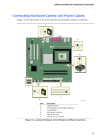
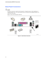
Installing and Replacing Desktop Board Components Connecting Hardware Control and Power Cables Figure 11 shows the location of the chassis intrusion and fan headers, and power connectors. A 1 B 1 2 C 1 F 1 2 1 E Item A B C D E F D Description Chassis rear fan 12 V processor core voltage connector Processor fan Main power connector Chassis front fan Chassis intrusion header OM17407 Figure 11. Location of Hardware Control Headers and Power Connectors 35
-
 1
1 -
2
-
3
-
4
-
5
-
6
-
7
-
8
-
9
-
10
-
11
-
12
-
13
-
14
-
15
-
16
-
17
-
18
-
19
-
20
-
21
-
22
-
23
-
24
-
25
-
26
-
27
-
28
-
29
-
 30
30 -
 31
31 -
 32
32 -
 33
33 -
 34
34 -
 35
35 -
 36
36 -
 37
37 -
 38
38 -
 39
39 -
 40
40 -
41
-
42
-
43
-
44
-
45
-
46
-
47
-
48
-
49
-
50
-
51
-
52
-
53
-
54
-
55
-
56
-
57
-
58
-
59
-
60
 |
 |

Installing and Replacing Desktop Board Components
35
Connecting Hardware Control and Power Cables
Figure 11 shows the location of the chassis intrusion and fan headers, and power connectors.
OM17407
1
1
1
2
1
1
2
A
B
C
D
E
F
Item
Description
A
Chassis rear fan
B
12 V processor core voltage connector
C
Processor fan
D
Main power connector
E
Chassis front fan
F
Chassis intrusion header
Figure 11.
Location of Hardware Control Headers and Power Connectors