Contents
vii
Figures
1.
Desktop Board D865PCK Components
.........................................................................
11
2.
LAN Connector LED Locations
.......................................................................................
16
3.
Installing the I/O Shield
...................................................................................................
24
4.
Location of Mounting Screw Holes
.................................................................................
25
5.
Installing a Processor
.....................................................................................................
26
6.
Connecting the Processor Fan Heat Sink Cable to the Processor Fan Connector
........
27
7.
Installing a DIMM
............................................................................................................
28
8.
Removing the AGP Card
................................................................................................
30
9.
Connecting the IDE Cable
..............................................................................................
31
10. Internal Headers
.............................................................................................................
32
11. Location of Hardware Control Headers and Power Connectors
.....................................
35
12. PCI Bus Add-in Card and Peripheral Interface Connectors
...........................................
37
13. Location of the BIOS Configuration Jumper Block
.........................................................
38
14. Back Panel Connectors
..................................................................................................
40
15. Removing the Battery
.....................................................................................................
45
16. F2 Key
............................................................................................................................
47
Tables
1.
Feature Summary
.............................................................................................................
9
2.
Desktop Board Components
..........................................................................................
12
3.
RJ-45 10/100 Ethernet LAN Connector LEDs
................................................................
16
4.
Front Panel Header
........................................................................................................
33
5.
USB 2.0 Header
.............................................................................................................
33
6.
Front Panel Audio Header Signal Names
.......................................................................
34
7.
Jumper Settings for the BIOS Setup Program Modes
....................................................
38
8.
Beep Codes
....................................................................................................................
51
9.
BIOS Error Messages
.....................................................................................................
52
10.
Safety Regulations
.........................................................................................................
55
11.
EMC Regulations
............................................................................................................
58
12.
Product Certification Markings
........................................................................................
59

 1
1 2
2 3
3 4
4 5
5 6
6 7
7 8
8 9
9 10
10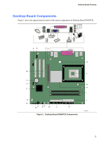 11
11 12
12