Intel D915PLWD English Product Guide
Intel D915PLWD Manual
 |
View all Intel D915PLWD manuals
Add to My Manuals
Save this manual to your list of manuals |
Intel D915PLWD manual content summary:
- Intel D915PLWD | English Product Guide - Page 1
Intel® Desktop Board D915PLWD Product Guide Order Number: D17259-001 - Intel D915PLWD | English Product Guide - Page 2
of the Intel® Desktop Board D915PLWD Product Guide. Date May 2005 If an FCC declaration of conformity marking is present on the board, the following energy and, if not installed and used in accordance with the instructions, may cause harmful interference to radio communications. However, there is - Intel D915PLWD | English Product Guide - Page 3
component installation, BIOS update, and regulatory requirements for Intel® Desktop Board D915PLWD. Intended Audience The Product Guide is intended for technically qualified personnel. Information Layout The chapters in this Product Guide are arranged as follows: 1 Desktop Board Features: a summary - Intel D915PLWD | English Product Guide - Page 4
Intel Desktop Board D915PLWD Product Guide Terminology The table below gives descriptions to some common terms used in the product guide. Term Description GB Gigabyte (1,073,741,824 bytes) GHz Gigahertz (one billion hertz) KB Kilobyte (1024 bytes) MB Megabyte (1,048,576 bytes) Mbit - Intel D915PLWD | English Product Guide - Page 5
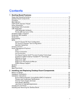
Contents 1 Desktop Board Features Supported Operating Systems 10 Desktop Board Components 11 Processor ...13 Main Memory ...14 Intel® 915PL Express Chipset 15 Audio Subsystem ...15 Input/Output (I/O) Controller 16 LAN Subsystem ...16 LAN Subsystem Software 16 RJ-45 LAN Connector LEDs 16 Hi- - Intel D915PLWD | English Product Guide - Page 6
Intel Desktop Board D915PLWD Product Guide Installing and Removing a Processor 28 Installing a Processor 28 Installing the Processor Fan Heat Sink 31 Removing the Processor 32 Installing and Removing Memory 32 Installing DIMMs...33 Removing DIMMs...34 Installing and Removing a PCI Express x16 - Intel D915PLWD | English Product Guide - Page 7
Location of the BIOS Configuration Jumper Block 45 24. Back Panel Connectors 47 25. Removing the Battery ...52 26. F2 Key ...53 Tables 1. Feature Summary...9 2. Desktop Board D915PLWD Components 12 3. Desktop Board D915PLWD Memory Configurations 14 4. RJ-45 10/100 Ethernet LAN Connector LEDs 17 - Intel D915PLWD | English Product Guide - Page 8
Intel Desktop Board D915PLWD Product Guide viii - Intel D915PLWD | English Product Guide - Page 9
main features of Intel® Desktop Board D915PLWD. Table 1 summarizes the major features of the desktop board. Table 1. Feature Summary Form Factor Processor Main Memory Chipset ATX (12.00" x 9.60") Support for: • Intel® Pentium® 4 processor in the LGA775 package • Intel® Celeron® D processor in the - Intel D915PLWD | English Product Guide - Page 10
Links: For more information about Intel Desktop Board D915PLWD, including the Technical Product Specification (TPS), BIOS updates, and device drivers, go to: http://support.intel.com/support/motherboards/desktop/ Supported Operating Systems The desktop board supports the following operating systems - Intel D915PLWD | English Product Guide - Page 11
Desktop Board Components Figure 1 shows the approximate location of the major components on desktop board D915PLWD. Line In RJ45 ABC DE F G H Intel® 82915PL U (MCH) I Intel® 82801FB Channel A DIMM 0 (ICH) Channel B T DIMM 0 S R Q P ONM L KJ Figure 1. Intel Desktop Board D915PLWD - Intel D915PLWD | English Product Guide - Page 12
• Intel Desktop Board D915PLWD http://www.intel.com/design/motherbd http://support.intel.com/support/motherboards/desktop • Supported processors http://support.intel.com/support/motherboards/desktop • Audio software and utilities http://www.intel.com/design/motherbd • LAN software and drivers - Intel D915PLWD | English Product Guide - Page 13
Board D915PLWD is located on the web at: http://support.intel.com/support/motherboards/desktop/ Related Links: Go to the following links or pages for more information about: • Supported Intel processors for Desktop Board D915PLWD http://support.intel.com/support/motherboards/desktop/ • Instructions - Intel D915PLWD | English Product Guide - Page 14
The desktop board supports dual or single channel memory configurations. Desktop Board D915PLWD supports dual or single channel memory configurations defined in Table 3. Table 3. Desktop Board D915PLWD Memory Configurations Memory Speed DDR 400 Processor Intel® Pentium® 4 processor Intel Pentium - Intel D915PLWD | English Product Guide - Page 15
Firmware Hub (FWH) Related Link: Go to the following link for more information about the Intel 915PL Express Chipset: http://developer.intel.com/design/nav/pcserver.htm Audio Subsystem Desktop Board D915PLWD • Audio drivers and utilities http://support.intel.com/support/motherboards/desktop/ • - Intel D915PLWD | English Product Guide - Page 16
transit threshold • Configurable EEPROM that contains the MAC address LAN Subsystem Software For LAN software and drivers, refer to the D915PLWD link on Intel's World Wide Web site at: http://support.intel.com/support/motherboards/desktop RJ-45 LAN Connector LEDs Two LEDs are built into the RJ-45 - Intel D915PLWD | English Product Guide - Page 17
meets the requirements for a full-speed USB device. The desktop board supports up to eight USB 2.0 ports via ICH6; four ports routed to the back panel and four routed to two internal USB 2.0 headers. USB 2.0 ports are backward compatible with USB 1.1 devices. USB 1.1 devices will function normally - Intel D915PLWD | English Product Guide - Page 18
Intel Desktop Board D915PLWD Product Guide Enhanced IDE Interface The ICH6's IDE interface handles the exchange of information between the processor and peripheral devices like hard disks, CD-ROM drives, and Iomega Zip* drives inside the computer. The interface supports: • Up to two IDE devices ( - Intel D915PLWD | English Product Guide - Page 19
to RAM (Instantly Available PC technology) ⎯ Resume on Ring ⎯ Wake from USB ⎯ Wake from PS/2 keyboard/mouse ⎯ PME# wakeup support ACPI ACPI gives the operating system direct control over the power management and Plug and Play functions of a computer. The use of ACPI with the desktop board requires - Intel D915PLWD | English Product Guide - Page 20
Intel Desktop Board D915PLWD Product Guide Fan Connectors The desktop board has a 4-pin processor fan header and two 3-pin chassis fan headers. See Figure 20 on page 42 for the location of the fan headers. Fan Speed Control (Intel® Precision Cooling Technology) Intel Precision Cooling Technology - Intel D915PLWD | English Product Guide - Page 21
on standby current requirements for the desktop board, refer to the Technical Product Specification by going to the following link, finding the product, and selecting Product Documentation from the left-hand menu: http://support.intel.com/support/motherboards/desktop/ Resume on Ring The operation of - Intel D915PLWD | English Product Guide - Page 22
Intel Desktop Board D915PLWD Product Guide Speaker A speaker is mounted on the desktop board. The speaker provides audible error code (beep code) information during the Power-On Self-Test (POST). Battery A battery on the desktop board keeps the values in CMOS RAM and the clock current when the - Intel D915PLWD | English Product Guide - Page 23
Components This chapter tells you how to: • Install the I/O shield • Install and remove the desktop board • Install and remove a processor and memory • Install and remove a PCI Express x16 card • Connect the IDE and Serial ATA cables • Connect internal headers • Set up flexible 6-channel audio with - Intel D915PLWD | English Product Guide - Page 24
Intel Desktop Board D915PLWD Product Guide Installation Precautions When you install and test the Intel desktop board, observe all warnings and cautions in the installation instructions. To avoid injury, be careful of: • Sharp pins on connectors • Sharp pins on printed circuit assemblies • Rough - Intel D915PLWD | English Product Guide - Page 25
Industry Canada statement at the front of this product guide demonstrates compliance with Canadian EMC regulations. Industry Canada recognizes local environmental regulations. There is insufficient space on this desktop board to provide instructions for replacing and disposing of the Lithium ion coin - Intel D915PLWD | English Product Guide - Page 26
Intel Desktop Board D915PLWD Product Guide Use Only for Intended Applications All Intel desktop boards are evaluated as supported without further evaluation by Intel. Related Links For information about regulatory compliance, go to Appendix B on page 61. Installing the I/O Shield The desktop board - Intel D915PLWD | English Product Guide - Page 27
Installing and Removing the Desktop Board Refer to your chassis manual for instructions on installing and removing the desktop board. Figure 5 shows the location of the 11 mounting screw holes for desktop board D915PLWD. OM17854 Figure 5. Desktop Board D915PLWD Mounting Screw Hole Locations - Intel D915PLWD | English Product Guide - Page 28
Intel Desktop Board D915PLWD Product Guide Installing and Removing a Processor Instructions on how to install the processor to the desktop board are given below. Installing a Processor CAUTION Before installing or removing the processor, make sure AC power has been removed by unplugging the power - Intel D915PLWD | English Product Guide - Page 29
Installing and Replacing Desktop Board Components 4. Remove the plastic protective socket cover from the load plate. Do not discard the protective socket cover. Always replace the socket cover if the processor is removed from the socket (see Figure 8, E). E OM17228 Figure 8. Remove the Protective - Intel D915PLWD | English Product Guide - Page 30
Intel Desktop Board D915PLWD Product Guide 6. Hold the processor with your thumb and index fingers oriented as shown in Figure 10. Make sure fingers align to the socket cutouts (see Figure 10, F). Align notches (see Figure 10, G) with the socket see (Figure 10, H). Lower the processor straight down - Intel D915PLWD | English Product Guide - Page 31
Installing the Processor Fan Heat Sink Desktop Board D915PLWD has an integrated processor fan heat sink retention mechanism (RM). For instructions on how to attach the processor fan heat sink to the integrated processor fan heat sink RM, refer to the boxed processor manual or the Intel World Wide - Intel D915PLWD | English Product Guide - Page 32
Intel Desktop Board D915PLWD Product Guide Removing the Processor For instruction on how to remove the processor fan heat sink and processor, refer to the processor installation manual or the Intel World Wide Web site at: The Boxed Intel® Pentium® 4 Processor in the 775-Land Package Installing and - Intel D915PLWD | English Product Guide - Page 33
Installing and Replacing Desktop Board Components Installing DIMMs CAUTION Install memory in the DIMM sockets prior to installing the PCI Express video card to avoid interference with the memory retention mechanism. 1. Observe the precautions in "Before You Begin" on page 23. 2. Turn off all - Intel D915PLWD | English Product Guide - Page 34
Intel Desktop Board D915PLWD Product Guide Removing DIMMs To remove a DIMM, follow these steps: 1. Observe the " on page 23. 2. Place the card in the PCI Express connector (Refer to the Intel Desktop Board D915PLWD Quick Reference). 3. Press down on the card until it is completely seated in the PCI - Intel D915PLWD | English Product Guide - Page 35
Installing and Replacing Desktop Board Components Removing the PCI Express Card Follow these instructions to remove the desktop board. The cable supports the ATA-66/100 transfer protocol. Figure 16 shows the correct installation of the cable. NOTE ATA-66/100 compatible cables are backward compatible - Intel D915PLWD | English Product Guide - Page 36
Intel Desktop Board D915PLWD Product Guide NOTE Do not connect an ATA device as a slave in "Before You Begin" on page 23. • Attach the cable end with the single connector to the Intel desktop board (Figure 16, A). • Attach the cable end with the two closely spaced connectors to the drives (Figure - Intel D915PLWD | English Product Guide - Page 37
the Serial ATA (SATA) Cable The SATA cable (4-conductor) supports the Serial ATA protocol and connects a single drive to the desktop board. Either end of the cable can be connected to the SATA drive or the connector on the board. For correct cable function: 1. Observe the precaution in "Before - Intel D915PLWD | English Product Guide - Page 38
Intel Desktop Board D915PLWD Product Guide Connecting Internal Headers Before connecting cables to the internal headers, observe the precautions in "Before You Begin" on page 23. Figure 18 shows the location - Intel D915PLWD | English Product Guide - Page 39
Installing and Replacing Desktop Board Components Installing a Front Panel Audio Solution Figure 18, E on page 38 shows the location of the yellow front panel audio header. Table 5 shows the pin - Intel D915PLWD | English Product Guide - Page 40
Intel Desktop Board D915PLWD Product Guide Connecting USB 2.0 Headers Before connecting the USB 2.0 headers, observe the precautions in "Before You Begin" on page 23. See Figure 18, D on page 38 for - Intel D915PLWD | English Product Guide - Page 41
Installing and Replacing Desktop Board Components Setting Up the Flexible 6-Channel Audio with Jack Re-tasking After installing the Realtek audio driver from the Intel Express Installer CD-ROM, the multichannel audio feature can be enabled. A B C Item A B C OM15694 Description Rear left/right - Intel D915PLWD | English Product Guide - Page 42
Intel Desktop Board D915PLWD Product Guide Connecting Fan and Power Cables Connecting Fan Cables Figure 20 shows the location of the fan headers. Connect the processor's fan heat sink cable to the 4-pin processor fan header on the board. Connect chassis fan cables to the 3-pin fan headers. 3 21 A - Intel D915PLWD | English Product Guide - Page 43
support the additional power requirements. Connecting 2x10 Power Supply Cables The 2x12 main power connector on the desktop board is backwards compatible in "Before You Begin" on page 23. 2. Connect the 12 V processor core voltage power supply cable to the 2x2 connector. 3. Connect the main - Intel D915PLWD | English Product Guide - Page 44
Intel Desktop Board D915PLWD Product Guide Other Connectors Figure 22 shows the location of the PCI bus add-in card connectors, PCI Express x1 add-in card connector, and peripheral interface connectors for Desktop Board D915PLWD. A B C D EFG Item A B C D E F G H I J J I H OM17862 Description - Intel D915PLWD | English Product Guide - Page 45
operation. Figure 23 shows the location of the desktop board's BIOS configuration jumper. 13 OM17863 Figure 23. Location of the BIOS Configuration Jumper Block The three-pin BIOS jumper block enables all board configurations to be done in BIOS Setup. Table 8 shows the jumper settings for the - Intel D915PLWD | English Product Guide - Page 46
Intel Desktop Board D915PLWD Product Guide Clearing Passwords This procedure assumes that the board is installed in the computer and the configuration jumper block is set to normal mode. 1. Observe the precautions in "Before You Begin" on page 23. 2. - Intel D915PLWD | English Product Guide - Page 47
Installing and Replacing Desktop Board Components Back Panel Connectors NOTE The line out connector, located on the back panel, is designed to power either headphones or amplified speakers only. Poor - Intel D915PLWD | English Product Guide - Page 48
Intel Desktop Board D915PLWD Product Guide Replacing the Battery A coin-cell battery (CR2032) powers the real-time clock and CMOS memory VSB applied. When the voltage drops below a certain level, the BIOS Setup program settings stored in CMOS RAM (for example, the date and time) might not be accurate - Intel D915PLWD | English Product Guide - Page 49
Installing and Replacing Desktop Board Components AVVERTIMENTO Esiste il pericolo di un esplosione se la pila non viene sostituita in modo corretto. Utilizzare solo pile uguali o di tipo equivalente a quelle - Intel D915PLWD | English Product Guide - Page 50
Intel Desktop Board D915PLWD Product Guide AWAS Risiko letupan wujud jika bateri digantikan dengan jenis yang tidak betul. Bateri sepatutnya dikitar semula jika boleh. Pelupusan bateri terpakai mestilah mematuhi peraturan alam - Intel D915PLWD | English Product Guide - Page 51
Installing and Replacing Desktop Board Components O ETTEVAATUST ATTENZJONI 51 - Intel D915PLWD | English Product Guide - Page 52
Intel Desktop Board D915PLWD Product Guide To replace the battery, follow these steps: 1. Observe the source (wall outlet or power adapter). 3. Remove the computer cover. 4. Locate the battery on the board (see Figure 25). 5. With a medium flat-bladed screwdriver, gently pry the battery free from its - Intel D915PLWD | English Product Guide - Page 53
. To update the BIOS with the Intel Express BIOS Update utility: 1. Go to the Intel World Wide Web site: http://support.intel.com/support/motherboards/desktop/ 2. Navigate to the D915PLWD page, click "[view] Latest BIOS updates," and select the Express BIOS Update utility file. 3. Download the file - Intel D915PLWD | English Product Guide - Page 54
to the Desktop Board D915PLWD page on the Intel World Wide Web site at: http://support.intel.com/support/motherboards/desktop Navigate to the D915PLWD page, click "[view] Latest BIOS updates," and select the Iflash BIOS Update utility file. NOTE Review the instructions distributed with the - Intel D915PLWD | English Product Guide - Page 55
steps explain how to recover the BIOS if an update fails. The following procedure uses recovery mode for the Setup program. See page 45 for more information on Setup modes. NOTE Because of the small amount of code available in the boot block area, there is no video support. You will not see anything - Intel D915PLWD | English Product Guide - Page 56
Intel Desktop Board D915PLWD Product Guide 56 - Intel D915PLWD | English Product Guide - Page 57
Error Messages and Indicators Desktop Board D915PLWD reports POST errors in two ways: • By sounding a beep code • By displaying an error message on the monitor BIOS Beep Codes The BIOS also issues a beep code (one long tone followed by two short tones) during POST if the video configuration fails - Intel D915PLWD | English Product Guide - Page 58
Intel Desktop Board D915PLWD Product Guide BIOS Error Messages When a recoverable error occurs during the POST, the BIOS displays an error message describing the problem. Table 10 gives an explanation of the BIOS error messages. Table 10. BIOS is incorrect. CMOS memory may have been corrupted - Intel D915PLWD | English Product Guide - Page 59
Error Messages and Indicators Table 43. BIOS Error Messages (continued) Error Message Memory Size Decreased Memory Size Increased Memory Size Changed No Boot Device Available Off Board Parity Error On Board Parity Error Parity Error NVRAM / CMOS / PASSWORD cleared by Jumper Pressed - Intel D915PLWD | English Product Guide - Page 60
Intel Desktop Board D915PLWD Product Guide 60 - Intel D915PLWD | English Product Guide - Page 61
• Electromagnetic Compatibility (EMC) regulations • Product certification markings Safety Regulations Desktop Board D915PLWD complies with the Conformity Statement We, Intel Corporation, declare under our sole responsibility that the product Intel® Desktop Board D915PLWD is in conformity with - Intel D915PLWD | English Product Guide - Page 62
Intel Desktop Board D915PLWD Product Guide Čeština Tento výrobek odpovídá požadavkům evropských směrnic 89/336/EEC a 73/23/EEC. Dansk Dette produkt er i overensstemmelse med det europæiske - Intel D915PLWD | English Product Guide - Page 63
the scope of covered products, available locations, shipping instructions, terms & conditions, etc. Intel Product Recycling Program http://www.intel.com/intel/other/ehs/product_ecology/Recycling_Program.htm Deutsch Als Teil von Intels Engagement für den Umweltschutz hat das Unternehmen das - Intel D915PLWD | English Product Guide - Page 64
Intel Desktop Board D915PLWD Product Guide Français Dans le cadre de son engagement pour la protection de l'environnement, Intel a mis en œuvre le programme Intel Product Recycling Program (Programme de recyclage des produits Intel) pour permettre aux consommateurs de produits Intel de recycler les - Intel D915PLWD | English Product Guide - Page 65
ılarını ögrenmek için lütfen http://www.intel.com/intel/other/ehs/product_ecology/Recycling_Program.htm Web sayfasına gidin. EMC Regulations Desktop Board D915PLWD complies with the EMC regulations stated in Table 12 when correctly installed in a compatible host system. Table 12. EMC Regulations - Intel D915PLWD | English Product Guide - Page 66
Intel Desktop Board D915PLWD Product Guide Japanese Kanji statement translation: this is a Class B product , it may cause radio interference. Install and use the equipment according to the instruction manual. Korean Class B statement translation: this is household equipment that is certified to - Intel D915PLWD | English Product Guide - Page 67
. For information about MIC certification, go to http://support.intel.com/support/motherboards/desktop/ Taiwan BSMI (Bureau of Standards, Metrology and Inspections) mark. Includes adjacent Intel company number, D33025. Printed wiring board manufacturer's recognition mark. Consists of a unique UL - Intel D915PLWD | English Product Guide - Page 68
Intel Desktop Board D915PLWD Product Guide 68
-
 1
1 -
 2
2 -
 3
3 -
 4
4 -
 5
5 -
 6
6 -
 7
7 -
8
-
9
-
10
-
11
-
12
-
13
-
14
-
15
-
16
-
17
-
18
-
19
-
20
-
21
-
22
-
23
-
24
-
25
-
26
-
27
-
28
-
29
-
30
-
31
-
32
-
33
-
34
-
35
-
36
-
37
-
38
-
39
-
40
-
41
-
42
-
43
-
44
-
45
-
46
-
47
-
48
-
49
-
50
-
51
-
52
-
53
-
54
-
55
-
56
-
57
-
58
-
59
-
60
-
61
-
62
-
63
-
64
-
65
-
66
-
67
-
68
 |
 |
Intel
®
Desktop Board
D915PLWD
Product Guide
Order Number:
D1725
9
-001