Intel D915PLWD English Product Guide - Page 7

Tables

Page 7 highlights

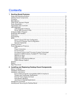
Contents 7. Lift the Load Plate and Don't Touch the Socket Contacts 28 8. Remove the Protective Socket Cover 29 9. Remove the Processor from the Protective Processor Cover/Do Not Touch 29 10. Install Processor ...30 11. Close the Load Plate ...30 12. Connecting the Processor Fan Heat Sink Cable to the Processor Fan Connector ........ 31 13. Memory Configuration Example 32 14. Installing a DIMM...33 15. Removing the PCI Express x16 Card 35 16. Connecting the IDE Cable 36 17. Connecting the Serial ATA Cable 37 18. Internal Headers ...38 19. Back Panel Audio Connectors for Flexible 6-Channel Audio System 41 20. Location of Fan Headers 42 21. Connecting Power Supply Cables 43 22. Location of the other Connectors on Desktop Board D915PLWD 44 23. Location of the BIOS Configuration Jumper Block 45 24. Back Panel Connectors 47 25. Removing the Battery ...52 26. F2 Key ...53 Tables 1. Feature Summary...9 2. Desktop Board D915PLWD Components 12 3. Desktop Board D915PLWD Memory Configurations 14 4. RJ-45 10/100 Ethernet LAN Connector LEDs 17 5. Front Panel Audio Header Signal Names 39 6. USB 2.0 Header Signal Names 40 7. Front Panel Header Signal Names 40 8. Jumper Settings for the BIOS Setup Program Modes 45 9. Beep Codes...57 10. BIOS Error Messages...58 11. Safety Regulations ...61 12. EMC Regulations...65 13. Product Certification Markings 67 vii

  • 1
  • 2
  • 3
  • 4
  • 5
  • 6
  • 7
  • 8
  • 9
  • 10
  • 11
  • 12
  • 13
  • 14
  • 15
  • 16
  • 17
  • 18
  • 19
  • 20
  • 21
  • 22
  • 23
  • 24
  • 25
  • 26
  • 27
  • 28
  • 29
  • 30
  • 31
  • 32
  • 33
  • 34
  • 35
  • 36
  • 37
  • 38
  • 39
  • 40
  • 41
  • 42
  • 43
  • 44
  • 45
  • 46
  • 47
  • 48
  • 49
  • 50
  • 51
  • 52
  • 53
  • 54
  • 55
  • 56
  • 57
  • 58
  • 59
  • 60
  • 61
  • 62
  • 63
  • 64
  • 65
  • 66
  • 67
  • 68

Contents
vii
7.
Lift the Load Plate and Don’t Touch the Socket Contacts
..............................................
28
8.
Remove the Protective Socket Cover
.............................................................................
29
9.
Remove the Processor from the Protective Processor Cover/Do Not Touch
.................
29
10. Install Processor
.............................................................................................................
30
11. Close the Load Plate
......................................................................................................
30
12. Connecting the Processor Fan Heat Sink Cable to the Processor Fan Connector
........
31
13. Memory Configuration Example
.....................................................................................
32
14. Installing a DIMM
............................................................................................................
33
15. Removing the PCI Express x16 Card
.............................................................................
35
16. Connecting the IDE Cable
..............................................................................................
36
17. Connecting the Serial ATA Cable
...................................................................................
37
18. Internal Headers
.............................................................................................................
38
19. Back Panel Audio Connectors for Flexible 6-Channel Audio System
............................
41
20. Location of Fan Headers
................................................................................................
42
21. Connecting Power Supply Cables
..................................................................................
43
22. Location of the other Connectors on Desktop Board D915PLWD
..................................
44
23. Location of the BIOS Configuration Jumper Block
.........................................................
45
24. Back Panel Connectors
..................................................................................................
47
25. Removing the Battery
.....................................................................................................
52
26. F2 Key
............................................................................................................................
53
Tables
1.
Feature Summary
.............................................................................................................
9
2.
Desktop Board D915PLWD Components
......................................................................
12
3.
Desktop Board D915PLWD Memory Configurations
......................................................
14
4.
RJ-45 10/100 Ethernet LAN Connector LEDs
................................................................
17
5.
Front Panel Audio Header Signal Names
.......................................................................
39
6.
USB 2.0 Header Signal Names
......................................................................................
40
7.
Front Panel Header Signal Names
.................................................................................
40
8.
Jumper Settings for the BIOS Setup Program Modes
....................................................
45
9.
Beep Codes
....................................................................................................................
57
10.
BIOS Error Messages
.....................................................................................................
58
11.
Safety Regulations
.........................................................................................................
61
12.
EMC Regulations
............................................................................................................
65
13.
Product Certification Markings
........................................................................................
67