Intel D945GPM English Product Guide
Intel D945GPM Manual
 |
View all Intel D945GPM manuals
Add to My Manuals
Save this manual to your list of manuals |
Intel D945GPM manual content summary:
- Intel D945GPM | English Product Guide - Page 1
Intel® Desktop Board D945GPM Product Guide Order Number: D21842-002 - Intel D945GPM | English Product Guide - Page 2
changes or modifications to the equipment not expressly approved by Intel Corporation could void the user's authority to operate the equipment. sustaining applications. Intel may make changes to specifications and product descriptions at any time, without notice. Desktop Board D945GPM may contain - Intel D945GPM | English Product Guide - Page 3
desktop board and other hardware components 3 Updating the BIOS: instructions on how to update the BIOS 4 Configuring for RAID (Intel® Matrix Storage Technology) Requires Serial ATA (SATA Hard Drives: information about configuring your system for RAID 5 Intel® Quick Resume Technology Driver (Intel - Intel D945GPM | English Product Guide - Page 4
• Intel Desktop Board D945GPM • I/O shield • One ATA-66/100 cable • Two locking Serial ATA cables • One diskette drive cable • One VGA port cover • Quick Reference poster • Configuration and battery caution statement label • Intel® Express Installer driver CD-ROM • Intel Express Installer software - Intel D945GPM | English Product Guide - Page 5
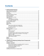
1 Desktop Board Features Supported Operating Systems 10 Desktop Board Components 11 Processor...13 Main Memory ...14 Intel® 945G Express Chipset 15 Graphics Subsystem ...15 Audio Subsystem ...15 Input/Output (I/O) Controller 16 LAN Subsystem ...16 LAN Subsystem Software 16 RJ-45 LAN Connector - Intel D945GPM | English Product Guide - Page 6
Intel Desktop Board D945GPM Product Guide Installing and Removing a Processor 28 Installing a Processor 28 Installing the Processor Fan Heat Sink 31 Connecting the Processor Fan Heat Sink Cable 31 Removing the Processor 31 Installing and Removing Memory 32 Installing DIMMs...34 Removing DIMMs - Intel D945GPM | English Product Guide - Page 7
Union Declaration of Conformity Statement 65 Product Ecology Statements 67 Lead-Free Desktop Board 69 EMC Regulations ...70 Product Certification Markings (Board Level 72 Figures 1. Desktop Board D945GPM Components 11 2. LAN Port LED Locations 16 3. Location of the Standby Power Indicator 20 - Intel D945GPM | English Product Guide - Page 8
Intel Desktop Board D945GPM Product Guide Tables 1. Feature Summary ...9 2. Desktop Boards D945GPM Components 12 3. Power Supply Requirements 13 4. Desktop Board D945GPM Memory Configurations 14 5. RJ-45 10/100/1000 Gigabit Ethernet LAN Connector LEDs 17 6. Front Panel Audio Header Signal Names - Intel D945GPM | English Product Guide - Page 9
of Intel® Desktop Board D945GPM. Table 1 summarizes the major features of the desktop board. Table 1. Feature Summary Form Factors Processor Main Memory Chipset Graphics Audio Expansion Capabilities Peripheral Interfaces MicroATX (9.6-inches x 9.6-inches) Support for an Intel® processor in - Intel D945GPM | English Product Guide - Page 10
For more information about desktop board D945GPM, including the Technical Product Specification (TPS), BIOS updates, and device drivers, go to: http://support.intel.com/support/motherboards/desktop/ Supported Operating Systems The desktop board supports the Microsoft Windows* XP Media Center Edition - Intel D945GPM | English Product Guide - Page 11
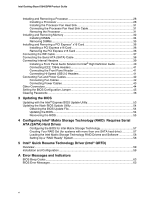
Figure 1 shows the approximate location of the major components on desktop board D945GPM. IEEE 1394a Line In Optical Line Out (Toslink) AB C D E T S Intel R 82945G (GMCH) IntelR 82801 (ICH7DH) R Q P O N M LK Channel B DIMM 0 Channel B DIMM 1 J Channel A DIMM 0 Channel A DIMM 1 I Figure - Intel D945GPM | English Product Guide - Page 12
: • Desktop board D945GPM http://www.intel.com/design/motherbd http://support.intel.com/support/motherboards/desktop • Supported processors http://support.intel.com/support/motherboards/desktop • Audio software and utilities http://www.intel.com/design/motherbd • LAN software and drivers http - Intel D945GPM | English Product Guide - Page 13
with the desktop board and must be purchased separately. The supported processors list for desktop board D945GPM is located on the web at: http://support.intel.com/support/motherboards/desktop/ Related Links: Go to the following links or pages for more information about: • Instructions on installing - Intel D945GPM | English Product Guide - Page 14
Intel Desktop Board D945GPM Product Guide Main Memory NOTE To be fully compliant with all applicable Intel® SDRAM memory specifications, the board should be populated with DIMMs that support the Serial Presence Detect (SPD) data structure. If your memory modules do not support SPD, you will see a - Intel D945GPM | English Product Guide - Page 15
) supporting Intel Matrix Storage Technology • Serial Peripheral Interface (SPI) Flash or Firmware Hub (FWH) Related Link: Go to the following link for more information about the Intel 945G Express Chipset: http://developer.intel.com/design/nav/pcserver.htm Graphics Subsystem Desktop board D945GPM - Intel D945GPM | English Product Guide - Page 16
Intel Desktop Board D945GPM Product Guide Related Links: Go to the following link or pages for more information about: • Audio drivers and utilities http://support.intel.com/support/motherboards/desktop/ • Installing the front panel audio solution, page 40 in Chapter 2 Input/Output (I/O) Controller - Intel D945GPM | English Product Guide - Page 17
Up to two IDE devices (such as hard drives) • ATAPI-style devices (such as CD-ROM drives) • Older PIO Mode devices • Ultra DMA-33 and ATA-66/100 protocols • Laser Servo (LS-120) drives Serial ATA The desktop board supports four Serial ATA channels (3.0 Gb/s) via the ICH7DH, connecting one device per - Intel D945GPM | English Product Guide - Page 18
Intel Desktop Board D945GPM Product Guide Expandability The desktop boards support the following: • One PCI Express x16 add-in card • One PCI Express x1 add-in card • Two PCI add-in cards Related Links: For information about installing the PCI Express x16 card, see page 36 in Chapter 2. BIOS The - Intel D945GPM | English Product Guide - Page 19
the desktop board BIOS. Disabling the processor fan speed control will result in the fan operating at full speed if it is not a self controlled fan. It is recommended that processor fan speed control remain enabled (default BIOS setting) when using the processor fan heat sink included with Intel - Intel D945GPM | English Product Guide - Page 20
Links: For more information on current standby requirements for the desktop board, refer to the Technical Product Specification by going to the following link, finding the product, and selecting Product Documentation from the left-hand menu: http://support.intel.com/support/motherboards/desktop/ 20 - Intel D945GPM | English Product Guide - Page 21
the Power-On Self-Test (POST). Battery A battery on the desktop board keeps the values in CMOS RAM and the clock current when the computer is turned off. Go to page 47 for instructions on how to replace the battery. Real-Time Clock The desktop board has a time-of-day clock and 100-year calendar. The - Intel D945GPM | English Product Guide - Page 22
Intel Desktop Board D945GPM Product Guide 22 - Intel D945GPM | English Product Guide - Page 23
desktop board • Install and remove a processor and memory • Install and remove a PCI Express x16 card • Connect the IDE and Serial ATA cables • Connect internal headers • Connect fans and power cables • Locate other connectors • Set the BIOS any telecommunications links, networks, or modems before - Intel D945GPM | English Product Guide - Page 24
test the Intel desktop board, observe all warnings and cautions in the installation instructions. To avoid injury, be careful of: • Sharp pins on connectors • Sharp pins on printed circuit assemblies • Rough edges and sharp corners on the chassis • Hot components (like processors, voltage regulators - Intel D945GPM | English Product Guide - Page 25
The Industry Canada statement at the front of this product guide demonstrates compliance with Canadian EMC regulations. Prevent Power Supply environmental regulations. There is insufficient space on this desktop board to provide instructions for replacing and disposing of the Lithium ion coin - Intel D945GPM | English Product Guide - Page 26
Intel Desktop Board D945GPM Product Guide Installing the I/O Shield The desktop board comes with an I/O shield. When installed promotes correct airflow within the chassis. Install the I/O shield before installing the desktop board in the chassis. Place the shield inside the chassis as shown in Figure - Intel D945GPM | English Product Guide - Page 27
result in personal injury or equipment damage. Refer to your chassis manual for instructions on installing and removing the desktop board. Figure 5 shows the location of the eight mounting screw holes for desktop board D945GPM. OM18103 Figure 5. Desktop Board D945GPM Mounting Screw Hole Locations 27 - Intel D945GPM | English Product Guide - Page 28
Intel Desktop Board D945GPM Product Guide Installing and Removing a Processor Instructions on how to install a processor to the desktop board are given below. Installing a Processor CAUTION Before installing or removing a processor, make sure the AC power has been removed by unplugging the power - Intel D945GPM | English Product Guide - Page 29
Installing and Replacing Desktop Board Components 4. Remove the plastic protective socket cover from the load plate (see Figure 8, E). Do not discard the protective socket cover. Always replace the socket cover if the processor is removed from the socket. E OM17228 Figure 8. Remove the Protective - Intel D945GPM | English Product Guide - Page 30
Intel Desktop Board D945GPM Product Guide 6. Hold the processor with your thumb and index fingers oriented as shown in Figure 10. Make sure fingers align to the socket cutouts (see Figure 10, F). Align notches (see Figure 10, G) with the socket see (Figure 10, H). Lower the processor straight down - Intel D945GPM | English Product Guide - Page 31
Installing the Processor Fan Heat Sink Desktop board D945GPM has an integrated processor fan heat sink retention mechanism (RM). For instructions on how to attach the processor fan heat sink to the integrated processor fan heat sink RM, refer to the boxed processor manual or the Intel World Wide - Intel D945GPM | English Product Guide - Page 32
Intel Desktop Board D945GPM Product Guide Installing and Removing Memory The desktop board has four 240-pin DDR2 DIMM sockets arranged as DIMM 0 (blue) and DIMM 1 (black) in both Channel A and Channel B. Guidelines for Dual Channel Memory Configuration Before installing DIMMs, read and follow these - Intel D945GPM | English Product Guide - Page 33
Installing and Replacing Desktop Board Components Three DIMMs Install a matched pair of DIMMs equal in speed and size in DIMM 0 (blue) and Channel A Channel B Figure 15. Dual Configuration Example 3 DIMM 0 DIMM 1 DIMM 0 DIMM 1 NOTE All other memory configurations will result in single channel - Intel D945GPM | English Product Guide - Page 34
Intel Desktop Board D945GPM Product Guide Installing DIMMs NOTE Install memory in the DIMM sockets prior to installing the PCI Express video card to avoid interference with the memory retention mechanism. 1. Observe the precautions in "Before You Begin" on page 23. 2. Turn off all peripheral devices - Intel D945GPM | English Product Guide - Page 35
Installing and Replacing Desktop Board Components 8. Insert the bottom edge of the DIMM into the socket. 9. the DIMM socket. The DIMM pops out of the socket. 7. Hold the DIMM by the edges, lift it away from the socket, and store it in an anti-static package. 8. Reinstall the PCI Express card if you - Intel D945GPM | English Product Guide - Page 36
Intel Desktop Board D945GPM Product Guide Installing and Removing a PCI Express* x16 Card CAUTION When installing any PCI Express x16 card on the desktop board Back Panel VGA Port Removing the PCI Express x16 Card Follow these instructions to remove the PCI Express x16 card from the RM: 1. Observe - Intel D945GPM | English Product Guide - Page 37
cable can connect two drives to the desktop board. The cable supports the ATA-66/100 transfer protocol. CD-ROM drive. For correct function of the cable: • Observe the precautions in "Before You Begin" on page 23. • Attach the cable end with the single connector (blue) to the Intel desktop board - Intel D945GPM | English Product Guide - Page 38
Intel Desktop Board D945GPM Product Guide Connecting the Serial ATA (SATA) Cable The SATA cable (4-conductor) supports the Serial ATA protocol and connects a single drive to the desktop board. For correct cable function (see Figure 19): 1. Observe the precaution in "Before You Begin" on page 23. 2. - Intel D945GPM | English Product Guide - Page 39
Installing and Replacing Desktop Board Components Connecting Internal Headers Before 87 65 43 21 No Connection Reset E HD LED Item A B C D E F Description Front panel audio IEEE 1394a (two) Chassis intrusion Alternate power LED Front panel Hi-speed USB 2.0 (two) Figure 20. Internal Headers OM18108 - Intel D945GPM | English Product Guide - Page 40
Intel Desktop Board D945GPM Product Guide Installing a Front Panel Audio Solution for Intel® High Definition Audio Figure 20, A on page 39 shows the location of the yellow front panel audio header. Table 6 shows the pin assignments for the front panel audio header. Table 6. Front Panel Audio - Intel D945GPM | English Product Guide - Page 41
Installing and Replacing Desktop Board Components Connecting IEEE 1394a Headers Before connecting the IEEE 1394a headers, observe the precautions in "Before You Begin" on page 23. See Figure 20, B on - Intel D945GPM | English Product Guide - Page 42
Intel Desktop Board D945GPM Product Guide Connecting Fan and Power Cables Connecting Fan Cables Figure 21 shows the location of the fan headers. Connect the processor's fan heat sink cable to the 4-pin processor fan header on the board. Connect chassis fan cables to the 3-pin fan headers. 43 2 1 A - Intel D945GPM | English Product Guide - Page 43
not connecting the 12 V (2x2) power connector to the desktop board may result in damage to the board or the system may not function properly. See Table 3 on in "Before You Begin" on page 23. 2. Connect the 12 V processor core voltage power supply cable to the 2x2 connector. 3. Connect the main power - Intel D945GPM | English Product Guide - Page 44
Intel Desktop Board D945GPM Product Guide Other Connectors Figure 23 shows the location of the PCI add-in card, PCI Express 1x, and diskette drive connectors. A BC D Item A B C D OM18111 Description PCI - Intel D945GPM | English Product Guide - Page 45
the location of the desktop board's BIOS configuration jumper. 32 1 OM18112 Figure 24. Location of the BIOS Configuration Jumper The three-pin BIOS jumper enables all board configurations to be done in BIOS Setup. Table 11 shows the jumper settings for the Setup program modes. Table 11. Jumper - Intel D945GPM | English Product Guide - Page 46
Intel Desktop Board D945GPM Product Guide Clearing Passwords This procedure assumes that the board is installed in the computer and the configuration jumper block is set to normal mode. 1. Observe the precautions in "Before You Begin" on page 23. 2. Turn off all peripheral devices connected to the - Intel D945GPM | English Product Guide - Page 47
Replacing Desktop Board Components Replacing the Battery A coin-cell battery (CR2032) powers the real-time clock and CMOS memory. When VSB applied. When the voltage drops below a certain level, the BIOS Setup program settings stored in CMOS RAM (for example, the date and time) might not be accurate - Intel D945GPM | English Product Guide - Page 48
Intel Desktop Board D945GPM Product Guide AVVERTIMENTO Esiste il pericolo di un esplosione se la pila non viene sostituita in modo corretto. Utilizzare solo pile uguali o di tipo equivalente a quelle consigliate - Intel D945GPM | English Product Guide - Page 49
Installing and Replacing Desktop Board Components AWAS Risiko letupan wujud jika bateri digantikan dengan jenis yang tidak betul. Bateri sepatutnya dikitar semula jika boleh. Pelupusan bateri terpakai mestilah mematuhi peraturan - Intel D945GPM | English Product Guide - Page 50
Intel Desktop Board D945GPM Product Guide O 50 - Intel D945GPM | English Product Guide - Page 51
Installing and Replacing Desktop Board Components To replace the battery, follow these steps: 1. Observe source (wall outlet or power adapter). 3. Remove the computer cover. 4. Locate the battery on the board (see Figure 25). 5. With a medium flat-bladed screwdriver, gently pry the battery free from - Intel D945GPM | English Product Guide - Page 52
Intel Desktop Board D945GPM Product Guide 52 - Intel D945GPM | English Product Guide - Page 53
of the Intel® Flash Memory Update Utility and the ease-of use of Windows-based installation wizards. To update the BIOS with the Intel Express BIOS Update utility: 1. Go to the Intel World Wide Web site: http://support.intel.com/support/motherboards/desktop/ 2. Navigate to the D945GPM page, click - Intel D945GPM | English Product Guide - Page 54
: • New BIOS files • BIOS recovery files • Intel Flash Memory Update Utility You can obtain the BIOS update file through your computer supplier or by navigating to the Desktop Board D945GPM page on the Intel World Wide Web site at: http://support.intel.com/support/motherboards/desktop Navigate to - Intel D945GPM | English Product Guide - Page 55
steps explain how to recover the BIOS if an update fails. The following procedure uses recovery mode for the Setup program. See page 45 for more information on Setup modes. NOTE Because of the small amount of code available in the boot block area, there is no video support. You will not see anything - Intel D945GPM | English Product Guide - Page 56
Intel Desktop Board D945GPM Product Guide 56 - Intel D945GPM | English Product Guide - Page 57
Technology (RAID) Requires Serial ATA (SATA) Hard Drives Configuring the BIOS for Intel Matrix Storage Technology 1. Assemble your system and attach one or more SATA hard drives. 2. Enter system BIOS Setup by pressing the key after the Power-On-Self-Test (POST) memory tests begin. 3. Go to - Intel D945GPM | English Product Guide - Page 58
the Windows installation and install all necessary drivers. 4. Install the Intel Matrix Storage Console software via the Intel Express Installer CD included with your desktop board or after downloading it from the Internet at http://support.intel.com/support/motherboards/desktop/. The Intel Matrix - Intel D945GPM | English Product Guide - Page 59
Quick Resume Technology Driver. Install the Intel Viiv software via the Intel® Express Installer Driver CD included with the desktop board or after downloading it from the Internet at http://support.intel.com/support/motherboards/desktop/. After the Intel Quick Resume Technology Driver is installed - Intel D945GPM | English Product Guide - Page 60
Intel Desktop Board D945GPM Product Guide 2. Select the Advanced tab. 3. Set the following Power buttons options: When I press the power button on my computer: Do nothing When I press the sleep button on my computer: Do nothing NOTE When using the Microsoft* Windows* XP Media Center Edition remote - Intel D945GPM | English Product Guide - Page 61
4. Select the Away tab. Intel Quick Resume Technology Driver 5. Verify the Enable Away mode is selected. 6. Verify the Return the computer from Away mode on mouse or keyboard activity is selected. If this is not selected, the Intel Viiv platform can only be turned on by pressing the power button - Intel D945GPM | English Product Guide - Page 62
Intel Desktop Board D945GPM Product Guide 62 - Intel D945GPM | English Product Guide - Page 63
A Error Messages and Indicators Desktop board D945GPM reports POST errors in two ways: • By sounding a beep code • By displaying an error message on the monitor BIOS Beep Codes The BIOS also issues a beep code (one long tone followed by two short tones) during POST if the video configuration fails - Intel D945GPM | English Product Guide - Page 64
Intel Desktop Board D945GPM Product Guide 64 - Intel D945GPM | English Product Guide - Page 65
- Safety - Part 1: General Requirements (International) European Union Declaration of Conformity Statement We, Intel Corporation, declare under our sole responsibility that the product Intel® Desktop Board D945GPM is in conformity with all applicable essential requirements necessary for CE marking - Intel D945GPM | English Product Guide - Page 66
Intel Desktop Board D945GPM Product Guide Čeština Tento výrobek odpovídá požadavkům evropských směrnic 89/336/EEC a 73/23/EEC. Dansk Dette produkt er i overensstemmelse med det europæiske - Intel D945GPM | English Product Guide - Page 67
scope of covered products, available locations, shipping instructions, terms and conditions, etc. Intel Product Recycling Program 请参考http://www.intel.com/intel/other/ehs/product_ecology/Recycling_Program.htm Deutsch Als Teil von Intels Engagement für den Umweltschutz hat das Unternehmen das - Intel D945GPM | English Product Guide - Page 68
Intel Desktop Board D945GPM Product Guide Français Dans le cadre de son engagement pour la protection de l'environnement, Intel a mis en œuvre le programme Intel Product Recycling Program (Programme de recyclage des produits Intel) pour permettre aux consommateurs de produits Intel de recycler les - Intel D945GPM | English Product Guide - Page 69
ayrıntılarını ögrenmek için lütfen http://www.intel.com/intel/other/ehs/product_ecology/Recycling_Program.htm web sayfasına gidin. Lead-Free Desktop Board This desktop board is lead free although certain discrete components used on the board contain a small amount of lead which is necessary for - Intel D945GPM | English Product Guide - Page 70
Intel Desktop Board D945GPM Product Guide EMC Regulations Desktop board D945GPM complies with the EMC regulations stated in Table 16 when correctly installed in a compatible host system. Table 16. EMC Regulations Regulation Title FCC Class B Title - Intel D945GPM | English Product Guide - Page 71
near a radio or television receiver in a domestic environment, it may cause radio interference. Install and use the equipment according to the instruction manual. Korean Class B statement translation: This is household equipment that is certified to comply with EMC requirements. You may use this - Intel D945GPM | English Product Guide - Page 72
Communication) mark. For information about MIC certification, go to http://support.intel.com/support/motherboards/desktop/ Taiwan BSMI (Bureau of Standards, Metrology and Inspections) mark. Includes adjacent Intel company number, D33025. Printed wiring board manufacturer's recognition mark. Consists
-
 1
1 -
 2
2 -
 3
3 -
 4
4 -
 5
5 -
 6
6 -
 7
7 -
8
-
9
-
10
-
11
-
12
-
13
-
14
-
15
-
16
-
17
-
18
-
19
-
20
-
21
-
22
-
23
-
24
-
25
-
26
-
27
-
28
-
29
-
30
-
31
-
32
-
33
-
34
-
35
-
36
-
37
-
38
-
39
-
40
-
41
-
42
-
43
-
44
-
45
-
46
-
47
-
48
-
49
-
50
-
51
-
52
-
53
-
54
-
55
-
56
-
57
-
58
-
59
-
60
-
61
-
62
-
63
-
64
-
65
-
66
-
67
-
68
-
69
-
70
-
71
-
72
 |
 |

Intel® Desktop Board D945GPM
Product Guide
Order Number:
D21842-002