Intel DC3217BY Technical Product Specification
Intel DC3217BY Manual
 |
View all Intel DC3217BY manuals
Add to My Manuals
Save this manual to your list of manuals |
Intel DC3217BY manual content summary:
- Intel DC3217BY | Technical Product Specification - Page 1
: G67688-002 The Intel Next Unit of Computing Board D33217CK may contain design defects or errors known as errata that may cause the product to deviate from published specifications. Current characterized errata are documented in the Intel Next Unit of Computing Board D33217CK Specification Update. - Intel DC3217BY | Technical Product Specification - Page 2
of any features or instructions marked "reserved" or "undefined." Intel reserves these for future definition and shall have no responsibility whatsoever for conflicts or incompatibilities arising from future changes to them. Intel Next Unit of Computing Boards may contain design defects - Intel DC3217BY | Technical Product Specification - Page 3
Next Unit of Computing Board D33217CK Identification Information AA Revision BIOS Revision Notes G69977-201 GKPPT10H.86A.0020 1,2 G69977-301 GKPPT10H.86A.0025 1,2 Notes: 1. The AA number is found on a small label on the component side of the board. 2. The Intel® QS77 PCH and Intel® Core™ i3 - Intel DC3217BY | Technical Product Specification - Page 4
Intel Desktop Board D33217CK Technical Product Specification iv - Intel DC3217BY | Technical Product Specification - Page 5
, connectors, power and environmental requirements, and the BIOS for Intel® Next Unit of Computing Board D33217CK. Intended Audience The TPS is intended to provide detailed, technical information about Intel Next Unit of Computing Board D33217CK and its components to the vendors, system integrators - Intel DC3217BY | Technical Product Specification - Page 6
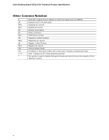
Intel Desktop Board D33217CK Technical Product Specification Other Common Notation # GB GB/s Gb/s KB Kb 048,576 bytes) Megabytes per second Megabit (1,048,576 bits) Megabits per second Thermal Design Power An address or data value ending with a lowercase h indicates a hexadecimal value. Volts. - Intel DC3217BY | Technical Product Specification - Page 7
Feature Summary 11 1.1.2 Board Layout (Top 13 1.1.3 Board Layout (Bottom 15 1.1.4 Block Diagram 17 1.2 Online Support 18 1.3 Processor 18 1.4 System Memory 19 1.4.1 Memory Configurations 20 1.5 Intel® QS77 Express Chipset 22 1.5.1 Direct Media Interface (DMI 22 1.5.2 Display Interfaces 22 - Intel DC3217BY | Technical Product Specification - Page 8
Intel Desktop Board D33217CK Technical Product Specification 2 Technical Reference 2.1 Memory Resources 33 2.1.1 Addressable Memory 33 2.1.2 Memory Map 35 2.2 Connectors and Headers 35 2.2.1 Back Panel Connectors 36 2.2.2 Connectors and Headers (Bottom 37 2.3 BIOS Setup Configuration Jumper - Intel DC3217BY | Technical Product Specification - Page 9
2. Major Board Components (Bottom 15 3. Block Diagram 17 4. Memory Channel and SO-DIMM Configuration 21 5. Thermal Solution and Fan Header 26 6. Location of the Standby Power LED 31 7. Detailed System Memory Address Map 34 8. Back Panel Connectors 36 9. Connectors and Headers (Bottom 37 10 - Intel DC3217BY | Technical Product Specification - Page 10
Intel Desktop Board D33217CK Technical Product Specification Tables 1. Feature Summary 11 2. Components Shown in Figure 1 14 3. Components Shown in Figure 2 16 4. Supported Memory Configurations 19 5. Effects of Pressing the Power Switch 27 6. Power States and Targeted System Power 28 7. Wake- - Intel DC3217BY | Technical Product Specification - Page 11
(101.60 millimeters by 101.60 millimeters) • Soldered-down Intel® Core™ i3-3217U processor with up to 17 W TDP ― Integrated graphics ― Integrated memory controller • Two 204-pin DDR3 SDRAM Small Outline Dual Inline Memory Module (SO-DIMM) sockets • Support for DDR3 1600 MHz, DDR3 1333 MHz, and DDR3 - Intel DC3217BY | Technical Product Specification - Page 12
Intel Desktop Board D33217CK Technical Product Specification Table 2. Feature Summary (continued) Hardware Monitor Subsystem Hardware monitoring subsystem, based on a Nuvoton NPCE791C embedded controller, including: • Voltage sense to detect out of range power supply voltages • Thermal sense to - Intel DC3217BY | Technical Product Specification - Page 13
Product Description 1.1.2 Board Layout (Top) Figure 1 shows the location of the major components on the top-side of Intel Next Unit of Computing Board D33217CK. Figure 1. Major Board Components (Top) 13 - Intel DC3217BY | Technical Product Specification - Page 14
Intel Desktop Board D33217CK Technical Product Specification Table 3 lists the components identified in Figure 1. Table 3. Components Shown in Figure 1 Item from Figure 1 A B Description Battery Standby power LED C Processor fan header D Onboard power button E Power LED F Hard Disk Drive - Intel DC3217BY | Technical Product Specification - Page 15
Product Description 1.1.3 Board Layout (Bottom) Figure 2 shows the location of the major components on the bottom-side of Intel Next Unit of Computing Board D33217CK. Figure 2. Major Board Components (Bottom) 15 - Intel DC3217BY | Technical Product Specification - Page 16
Intel Desktop Board D33217CK Technical Product Specification Table 4. Components Shown in Figure 2 Item from Figure 2 Description A Back panel connectors B PCI Express Full-Mini Card connector C PCI Express Half-Mini Card connector D Front panel dual-port USB 2.0 header E BIOS setup - Intel DC3217BY | Technical Product Specification - Page 17
Product Description 1.1.4 Block Diagram Figure 3 is a block diagram of the major functional areas of the board. Figure 3. Block Diagram 17 - Intel DC3217BY | Technical Product Specification - Page 18
.com/support/motherboards/desktop/sb/CS025414.htm http://www.intel.com/support/go/buildit 1.3 Processor The board has a soldered-down Intel Core i3-3217U processor with Integrated Graphics Technology and integrated memory controller. NOTE This board has specific requirements for providing power to - Intel DC3217BY | Technical Product Specification - Page 19
memory specifications, the board should be populated with SO-DIMMs that support the Serial Presence Detect (SPD) data structure. This allows the BIOS to read the SPD data and program the chipset to accurately configure memory settings for optimum performance. If non-SPD memory is installed, the BIOS - Intel DC3217BY | Technical Product Specification - Page 20
Intel Desktop Board D33217CK Technical Product Specification For information about... Tested Memory Refer to: http://support.intel.com/support/motherboards/desktop/sb /CS-025414.htm 1.4.1 Memory Configurations The processor supports the following types of memory installed or the memory capacities - Intel DC3217BY | Technical Product Specification - Page 21
Product Description Figure 4 illustrates the memory channel and SO-DIMM configuration. Figure 4. Memory Channel and SO-DIMM Configuration 21 - Intel DC3217BY | Technical Product Specification - Page 22
Intel Desktop Board D33217CK Technical Product Specification 1.5 Intel® QS77 Express Chipset Intel QS77 Express Chipset with Direct Media Interface (DMI) interconnect provides interfaces to the processor and the USB, SATA, LPC, LAN, and PCI Express interfaces. The Intel QS77 Express Chipset is a - Intel DC3217BY | Technical Product Specification - Page 23
HDMI 1.4a Dynamic Video Memory Technology (DVMT) 5.0 support Support of up to 1.7 GB Video Memory with 4 GB and above system memory configuration 1.6.1.2 Video Memory Allocation Intel® Dynamic Video Memory Technology (DVMT) is a method for dynamically allocating system memory for use as graphics - Intel DC3217BY | Technical Product Specification - Page 24
operating systems. 1.7.1 AHCI Mode The board supports AHCI storage mode via the Intel QS77 Express Chipset. NOTE In order to use AHCI mode, AHCI must be enabled in the BIOS. Also, during Microsoft Windows XP installation, F6 must be pressed to install the AHCI drivers. See your Microsoft Windows XP - Intel DC3217BY | Technical Product Specification - Page 25
controller switches between the two protocols to support communications over a single cable. Thunderbolt technology is implemented on Intel Desktop Board D33217CK as a plug and play interface. No software drivers are required. 1.10 Hardware Management Subsystem The hardware management features - Intel DC3217BY | Technical Product Specification - Page 26
Intel Desktop Board D33217CK Technical Product Specification 1.10.1 Hardware Monitoring The hardware monitoring and fan control subsystem is based on a Nuvoton NPCE791C embedded controller, which supports the following: • Processor and system ambient temperature monitoring • Chassis fan speed - Intel DC3217BY | Technical Product Specification - Page 27
(some add-in boards may require an ACPI-aware driver), video displays, and hard disk drives • Methods for achieving less than 15-watt system operation in the power-on/standby sleeping state • A Soft-off feature that enables the operating system to power-off the computer • Support for multiple wake - Intel DC3217BY | Technical Product Specification - Page 28
or external source. No power to the system. Service can be performed safely. Notes: 1. Total system power is dependent on the system configuration, including add-in boards and peripherals powered by the system chassis' power supply. 2. Dependent on the standby power consumption of wake-up devices - Intel DC3217BY | Technical Product Specification - Page 29
system that provides full ACPI support. In addition, software, drivers, and peripherals must fully support ACPI wake events. 1.11.2 Hardware Support The board provides several power management hardware features, including: • Wake from Power Button signal • Instantly Available PC technology • LAN - Intel DC3217BY | Technical Product Specification - Page 30
The use of Instantly Available PC technology requires operating system support and drivers for any installed PCI Express add-in card. 1.11.2.3 LAN Wake Capabilities LAN wake capabilities enable remote wake-up of the computer through a network. The LAN subsystem monitors network traffic at the Media - Intel DC3217BY | Technical Product Specification - Page 31
present even when the computer appears to be off. Figure 6 shows the location of the standby power LED. CAUTION If AC power has been switched off and the standby power indicator is still lit, disconnect the power cord before installing or removing any devices connected to the board. Failure to do so - Intel DC3217BY | Technical Product Specification - Page 32
Intel Desktop Board D33217CK Technical Product Specification 32 - Intel DC3217BY | Technical Product Specification - Page 33
the top of DRAM (total system memory). On a system that has 16 GB of system memory installed, it is not possible to use all of the installed memory due to system address space being allocated for other system critical functions. These functions include the following: • BIOS/SPI Flash device (16 Mbit - Intel DC3217BY | Technical Product Specification - Page 34
Intel Desktop Board D33217CK Technical Product Specification Figure 7. Detailed System Memory Address Map 34 - Intel DC3217BY | Technical Product Specification - Page 35
headers are not overcurrent protected and should connect only to devices inside the computer's chassis, such as fans and internal peripherals. Do not use these connectors or headers to power devices external to the computer's chassis. A fault in the load presented by the external devices could cause - Intel DC3217BY | Technical Product Specification - Page 36
Intel Desktop Board D33217CK Technical Product Specification 2.2.1 Back Panel Connectors Figure 8 shows the location of the back panel connectors for the board. Item A B C D E Description Thunderbolt connector HDMI connector USB 2.0 port USB 2.0 port 19 V DC input jack Figure 8. Back Panel - Intel DC3217BY | Technical Product Specification - Page 37
Technical Reference 2.2.2 Connectors and Headers (Bottom) Figure 9 shows the locations of the connectors and headers on the bottom-side of the board. Figure 9. Connectors and Headers (Bottom) 37 - Intel DC3217BY | Technical Product Specification - Page 38
Intel Desktop Board D33217CK Technical Product Specification Table 10 lists the connectors and headers identified in Figure 9. Table 10. Connectors and Headers Shown in Figure 9 Item from Figure 9 Description A PCI Express Full-Mini Card connector B PCI Express Half-Mini Card connector C - Intel DC3217BY | Technical Product Specification - Page 39
and Headers Table 11. PCI Express Full-Mini Card Connector Pin Signal Name Additional Signal Name 1 WAKE# 2 3.3 V 3 Reserved (Extra USB) +5 V_MINI 4 GND 5 Reserved (Extra USB) CARDIN 6 1.5 V 7 CLKREQ# 8 Reserved 9 GND 10 Reserved 11 REFCLK- 12 Reserved 13 REFCLK+ 14 - Intel DC3217BY | Technical Product Specification - Page 40
Intel Desktop Board D33217CK Technical Product Specification Table 11. PCI Express Full-Mini Card Connector (continued) 7 Ground 8 Ground 9 KEY (no pin) 10 No Connect 2.2.2.2 Add-in Card Connectors The board has the following add-in card connectors: • One PCI Express Half-Mini Card • One - Intel DC3217BY | Technical Product Specification - Page 41
is 10 A. • Internal Power Supply - the board can alternatively be powered via the internal 19 V DC 1 x 2 power connector, where pin 1 is GND and pin 2 is +19 (±10%) VDC. Table 13. 19 V Internal Power Supply Connector Pin Signal Name 1 Ground 2 +19 V (±10%) For information about Power supply - Intel DC3217BY | Technical Product Specification - Page 42
drive connected to an onboard SATA connector. 2.2.2.4.2 Reset Switch Header Pins 5 and 7 can be connected to a momentary single pole, single throw (SPST) type switch that is normally open. When the switch is closed, the board resets and runs the POST. 2.2.2.4.3 Power/Sleep LED Header Pins - Intel DC3217BY | Technical Product Specification - Page 43
is due to internal debounce circuitry on the board.) At least two seconds must pass before the power supply will recognize another on/off signal. header. NOTE • The +5 V DC power on the USB header is fused. • Use only a front panel USB connector that conforms to the USB 2.0 specification for - Intel DC3217BY | Technical Product Specification - Page 44
Intel Desktop Board D33217CK Technical Product Specification 2.3 BIOS Setup Configuration Jumper CAUTION Do not move a jumper with the power on. Always turn off the power and unplug the power cord from the computer before changing a jumper setting. Otherwise, the board could be damaged. Figure 12 - Intel DC3217BY | Technical Product Specification - Page 45
. After the POST runs, Setup runs automatically. The maintenance menu is displayed. Note that this Configure mode is the only way to clear the BIOS/CMOS settings. Press F9 (restore defaults) while in Configure mode to restore the BIOS/CMOS settings to their default values. Recovery None The - Intel DC3217BY | Technical Product Specification - Page 46
Intel Desktop Board D33217CK Technical Product Specification 2.4 Mechanical Considerations 2.4.1 Form Factor The board is designed to fit into a custom chassis. Figure 13 illustrates the mechanical form factor for the board. Dimensions are given in inches [millimeters]. The outer dimensions are 4.0 - Intel DC3217BY | Technical Product Specification - Page 47
external 19 V DC jack is the primary power input connector of Intel Next Unit of Computing Board D33217CK. However, the board also provides an internal 1 x 2 power connector that can be used in custom-developed systems that have an internal power supply. There is no isolation circuitry between the - Intel DC3217BY | Technical Product Specification - Page 48
or, in some instances, damage to the board. All responsibility for determining the adequacy of any thermal or system design remains solely with the system integrator. Intel makes no warranties or representations that merely following the instructions presented in this document will result in - Intel DC3217BY | Technical Product Specification - Page 49
Technical Reference Figure 14 shows the locations of the localized high temperature zones. Item A B Description Processor voltage regulator area Thermal solution Figure 14. Localized High Temperature Zones 49 - Intel DC3217BY | Technical Product Specification - Page 50
board. Table 18. Thermal Considerations for Components Component Maximum Case Temperature Processor Intel QS77 power dissipation equal to Thermal Design Power (TDP is specified as the maximum sustainable power to that the temperature measurement in the system BIOS is a value reported by embedded - Intel DC3217BY | Technical Product Specification - Page 51
is used to estimate repair rates and spare parts requirements. The MTBF for the board is 62,504 hours. 2.8 Environmental Table 20 lists the environmental specifications for the board. Table 20. Environmental Specifications Parameter Temperature Non-Operating Operating Shock Unpackaged Packaged - Intel DC3217BY | Technical Product Specification - Page 52
Intel Desktop Board D33217CK Technical Product Specification 52 - Intel DC3217BY | Technical Product Specification - Page 53
used to view and change the BIOS settings for the computer. The BIOS Setup program is accessed by pressing the key after the Power-On Self-Test (POST) memory test begins and before the operating system boot begins. NOTE The maintenance menu is displayed only when the board is in configure mode - Intel DC3217BY | Technical Product Specification - Page 54
USB drivers are not yet available. Legacy USB support is used to access the BIOS Setup program, and to install an operating system that supports USB. By default, Legacy USB support is set to Enabled. Legacy USB support operates as follows: 1. When you apply power to the computer, legacy support is - Intel DC3217BY | Technical Product Specification - Page 55
BIOS matches the target system to prevent accidentally installing an incompatible BIOS. NOTE Review the instructions distributed with the upgrade utility before attempting a BIOS update. For information about BIOS update utilities Refer to http://support.intel.com/support/motherboards/desktop - Intel DC3217BY | Technical Product Specification - Page 56
is bigger than 1.4 MB size limit) NOTE Supported file systems for BIOS recovery: • NTFS (sparse, compressed, or encrypted files are not supported) • FAT32 • FAT16 • FAT12 • ISO 9660 For information about BIOS recovery Refer to http://www.intel.com/support/motherboards/desktop/sb/cs-023360.htm 56 - Intel DC3217BY | Technical Product Specification - Page 57
hard drive second and removable drive third. 3.7.1 Booting Without Attached Devices For use in embedded applications, the BIOS has been designed so that after passing the POST, the operating system loader is invoked even if the following devices are not present: • Video adapter • Keyboard • Mouse - Intel DC3217BY | Technical Product Specification - Page 58
Password Entry Error A manual power cycle will be required to resume system operation. NOTE As implemented on D33217CK, Hard Disk Drive Password Security is only supported on SATA port 0. The passwords are stored on the hard disk drive so if the drive is relocated to another computer that does not - Intel DC3217BY | Technical Product Specification - Page 59
includes security features that restrict access to the BIOS Setup program and who can boot the computer. A supervisor password and a user password can be set for the BIOS Setup program and for booting the computer, with the following restrictions: • The supervisor password gives unrestricted access - Intel DC3217BY | Technical Product Specification - Page 60
Intel Desktop Board D33217CK Technical Product Specification 60 - Intel DC3217BY | Technical Product Specification - Page 61
LED Blink Codes Whenever a recoverable error occurs during POST, the BIOS causes the board's front panel power LED to blink an error message describing the problem (see Table 25). Table 25. Front-panel Power LED Blink Codes Type Pattern BIOS update in progress Video error (Note) Off when the - Intel DC3217BY | Technical Product Specification - Page 62
Intel Desktop Board D33217CK Technical Product Specification 4.3 Port 80h POST Codes During the POST, the BIOS generates execution 0x21 - 0x29 MRC memory detection 0x2A - 0x2F PEI phase post MRC execution 0x31 - 0x35 Recovery 0x36 - 0x3F Platform DXE driver 0x41 - 0x4F CPU Initialization - Intel DC3217BY | Technical Product Specification - Page 63
Security Phase (SEC) 0x08 Starting BIOS execution after CPU BIST 0x09 SPI prefetching core PEI before MRC PEI Platform driver 0x11 Set bootmode, GPIO init 0x12 Early chipset register programming including graphics init 0x13 Basic PCH init, discrete device init (IEEE 1394, SATA) 0x14 LAN - Intel DC3217BY | Technical Product Specification - Page 64
Intel Desktop Board D33217CK Technical Product Specification Table 28. Port 80h POST Codes 0x52 Allocating resources to PCI bus Hot Plug PCI controller initialization USB 0x58 Resetting USB bus 0x59 Reserved for USB ATA/ATAPI/SATA 0x5A Resetting PATA/SATA bus and all devices 0x5B Reserved - Intel DC3217BY | Technical Product Specification - Page 65
Progress Code Enumeration BDS BDS driver entry point initialize BDS service routine entry point (can be core (should not get here) Keyboard (PS/2 or USB) Resetting keyboard Disabling the keyboard Detecting the presence of the keyboard Enabling the keyboard Clearing keyboard input buffer Instructing - Intel DC3217BY | Technical Product Specification - Page 66
Intel Desktop Board D33217CK Technical Product Specification Table 28. Port 80h POST Codes ( Core 0xE4 0xE7 Entered DXE phase Waiting for user input BDS 0xE8 Checking password 0xE9 Entering BIOS setup 0xEB Calling Legacy Option ROMs Runtime Phase/EFI OS Boot 0xF8 EFI boot service - Intel DC3217BY | Technical Product Specification - Page 67
presence of the keyboard 90 Resetting keyboard 94 Clearing keyboard input buffer 95 Keyboard Self Test EB Calling Video BIOS 58 Resetting USB bus 5A Resetting PATA/SATA bus and all devices 92 Detecting the presence of the keyboard 90 Resetting keyboard 94 Clearing keyboard input - Intel DC3217BY | Technical Product Specification - Page 68
Intel Desktop Board D33217CK Technical Product Specification 68 - Intel DC3217BY | Technical Product Specification - Page 69
Compatibility (EMC) standards • Product certification markings 5.1.1 Safety Standards Intel Next Unit of Computing Board D33217CK complies with the safety standards stated in Table 30 when correctly installed in a compatible host system. Table 30. Safety Standards Standard Title CSA/UL 60950 - Intel DC3217BY | Technical Product Specification - Page 70
5.1.2 European Union Declaration of Conformity Statement We, Intel Corporation, declare under our sole responsibility that the products Intel® Next Unit of Computing Board D33217CK is in conformity with all applicable essential requirements necessary for CE marking, following the provisions of the - Intel DC3217BY | Technical Product Specification - Page 71
of this program, including the scope of covered products, available locations, shipping instructions, terms and conditions, etc Intel Product Recycling Program http://www.intel.com/intel/other/ehs/product_ecology Deutsch Als Teil von Intels Engagement für den Umweltschutz hat das Unternehmen das - Intel DC3217BY | Technical Product Specification - Page 72
les adresses disponibles, les instructions d'expédition, les conditions générales, etc. 日本語 http://www.intel.com/in tel/other/ ao ambiente, a Intel implementou o Programa de Reciclagem de Produtos para que os consumidores finais possam enviar produtos Intel usados para locais selecionados - Intel DC3217BY | Technical Product Specification - Page 73
/other/ehs/product_ecology Web sayfasına gidin. 5.1.4 EMC Regulations Intel Next Unit of Computing Board D33217CK complies with the EMC regulations stated in Table 31 when correctly installed in a compatible host system. Table 31. EMC Regulations Regulation Title FCC 47 CFR Part 15, Subpart - Intel DC3217BY | Technical Product Specification - Page 74
installation. This equipment generates, uses, and can radiate radio frequency energy and, if not installed and used in accordance with the instructions Any changes or modifications to the equipment not expressly approved by Intel Corporation could void the user's authority to operate the equipment. - Intel DC3217BY | Technical Product Specification - Page 75
(VCCI). If this is used near a radio or television receiver in a domestic environment, it may cause radio interference. Install and use the equipment according to the instruction manual. Korea Class B Statement Korea Class B Statement translation: This equipment is for home use, and has acquired - Intel DC3217BY | Technical Product Specification - Page 76
two governmental agencies in the definition of new requirements. Intel Next Unit of Computing Board D33217CK meets the following program requirements in an adequate system configuration, including appropriate selection of an efficient power supply: • Energy Star v5.2, category B • EPEAT* • Korea - Intel DC3217BY | Technical Product Specification - Page 77
Logo: This is an example of the symbol used on Intel Next Unit of Computing Boards and associated collateral. The color of the mark may vary depending upon the application. The Environmental Friendly Usage Period (EFUP) for Intel Next Unit of Computing Boards has been determined to be 10 years. 77 - Intel DC3217BY | Technical Product Specification - Page 78
5.2 Battery Disposal Information CAUTION Risk of explosion if the battery is replaced with an incorrect type. Batteries should be recycled where possible. Disposal of used batteries must be in accordance with local environmental regulations. PRÉCAUTION Risque d'explosion si la pile usagée est - Intel DC3217BY | Technical Product Specification - Page 79
Regulatory Compliance and Battery Disposal Information PRECAUCIÓN Existe peligro de explosión si la pila no se cambia de forma adecuada. Utilice solamente pilas iguales o del mismo tipo que las recomendadas por el fabricante del equipo. Para deshacerse de las pilas usadas, siga igualmente las - Intel DC3217BY | Technical Product Specification - Page 80
AWAS Risiko letupan wujud jika bateri digantikan dengan jenis yang tidak betul. Bateri sepatutnya dikitar semula jika boleh. Pelupusan bateri terpakai mestilah mematuhi peraturan alam sekitar tempatan. OSTRZEŻENIE Istnieje niebezpieczeństwo wybuchu w przypadku zastosowania niewłaściwego typu baterii - Intel DC3217BY | Technical Product Specification - Page 81
Regulatory Compliance and Battery Disposal Information 81 - Intel DC3217BY | Technical Product Specification - Page 82
82
-
 1
1 -
 2
2 -
 3
3 -
 4
4 -
 5
5 -
 6
6 -
 7
7 -
8
-
9
-
10
-
11
-
12
-
13
-
14
-
15
-
16
-
17
-
18
-
19
-
20
-
21
-
22
-
23
-
24
-
25
-
26
-
27
-
28
-
29
-
30
-
31
-
32
-
33
-
34
-
35
-
36
-
37
-
38
-
39
-
40
-
41
-
42
-
43
-
44
-
45
-
46
-
47
-
48
-
49
-
50
-
51
-
52
-
53
-
54
-
55
-
56
-
57
-
58
-
59
-
60
-
61
-
62
-
63
-
64
-
65
-
66
-
67
-
68
-
69
-
70
-
71
-
72
-
73
-
74
-
75
-
76
-
77
-
78
-
79
-
80
-
81
-
82
 |
 |

Intel® Next Unit of Computing
Board D33217CK
Technical Product Specification
October 2012
Order Number:
G67688-002
The Intel Next Unit of Computing Board D33217CK may contain design defects or errors known as errata that may cause the product to deviate from
published specifications.
Current characterized errata are documented in the Intel Next Unit of Computing Board D33217CK Specification Update.