Intel DP55KG Product Guide - Page 51
S/PDIF Header, Front Panel Intel HD Audio Header, Consumer IR (CIR) Headers
 |
UPC - 735858205979
View all Intel DP55KG manuals
Add to My Manuals
Save this manual to your list of manuals |
Page 51 highlights
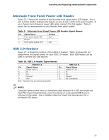
Installing and Replacing Desktop Board Components S/PDIF Header Figure 27, A shows the location of the S/PDIF output header. Table 4 shows the pin assignments and signal names for the S/PDIF connector. Table 4. S/PDIF Header Signal Names Pin Description 1 Ground 2 S/PDIF Out 3 Key (no pin) 4 +5 VDC Front Panel Intel HD Audio Header Figure 27, B shows the location of the front panel Intel HD Audio header. Table 5 shows the pin assignments and signal names for the front panel Intel HD Audio header. Table 5. Front Panel Intel HD Audio Header Signal Names Pin Signal Name 1 PORT 1L 3 PORT 1R 5 PORT 2R 7 SENSE_SEND 9 PORT 2L Pin Signal Name 2 GND 4 PRESENCE# 6 SENSE1_RETURN 8 KEY (no pin) 10 SENSE2_RETURN Consumer IR (CIR) Headers The Desktop Board has two CIR headers: the input or receiver header (Figure 27, C) and the output or emitter header (Figure 27, D). The receiver header consists of a filtered translated infrared input compliant with Microsoft CIR specifications and a "learning" infrared input. The learning input is a high-pass input which the computer can use to "learn" to speak the infrared communication language of other user remotes. The emitter header consists of two output ports which the computer can use to emulate "learned" infrared commands in order to control external electronic hardware. NOTE The Consumer IR option must be enabled in the system BIOS before it can function. Press at boot to enter the system BIOS, and go to Advanced > Peripheral Configuration > Enhanced Consumer IR, and set this option to Enabled. 51
-
 1
1 -
2
-
3
-
4
-
5
-
6
-
7
-
8
-
9
-
10
-
11
-
12
-
13
-
14
-
15
-
16
-
17
-
18
-
19
-
20
-
21
-
22
-
23
-
24
-
25
-
26
-
27
-
28
-
29
-
30
-
31
-
32
-
33
-
34
-
35
-
36
-
37
-
38
-
39
-
40
-
41
-
42
-
43
-
44
-
45
-
 46
46 -
 47
47 -
 48
48 -
 49
49 -
 50
50 -
 51
51 -
 52
52 -
 53
53 -
 54
54 -
 55
55 -
 56
56 -
57
-
58
-
59
-
60
-
61
-
62
-
63
-
64
-
65
-
66
-
67
-
68
-
69
-
70
-
71
-
72
-
73
-
74
-
75
-
76
-
77
-
78
-
79
-
80
-
81
-
82
-
83
-
84
-
85
-
86
-
87
-
88
-
89
-
90
-
91
-
92
 |
 |
