Intel DP67BG Product Guide - Page 35
Remove the Processor from the Protective Cover, Install the Processor - will not post
 |
View all Intel DP67BG manuals
Add to My Manuals
Save this manual to your list of manuals |
Page 35 highlights
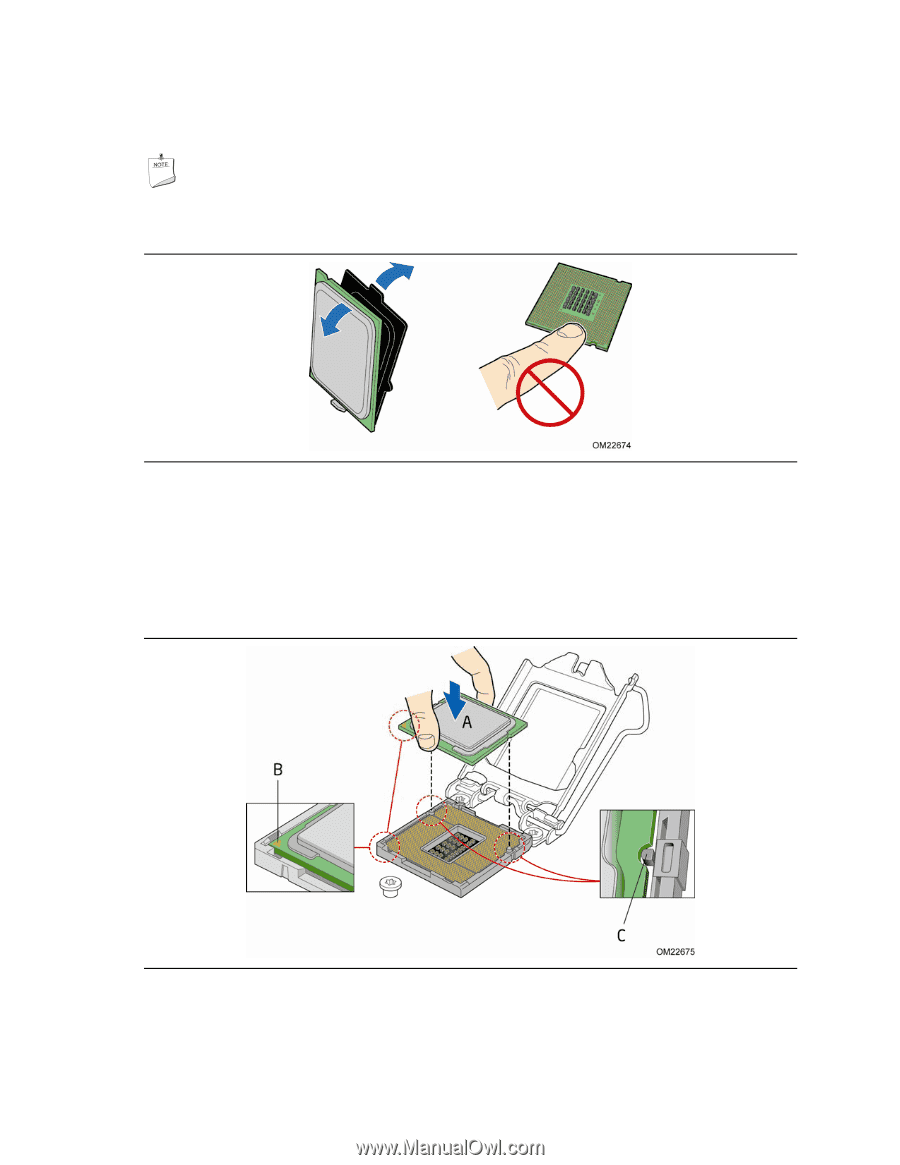
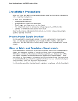
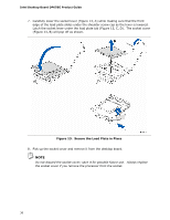
Installing and Replacing Desktop Board Components 4. Remove the processor from its protective cover. Hold the processor only at the edges, being careful not to touch the bottom of the processor (see Figure 11). NOTE Do not discard the processor cover. Always replace the processor cover if you remove the processor from the socket. Figure 11. Remove the Processor from the Protective Cover 5. Hold the processor with your thumb and index finger oriented as shown in Figure 12 to align your fingers with the socket finger cutouts. Make sure that the processor Pin 1 indicator (gold triangle) is aligned with the Pin 1 chamfer on the socket (Figure 12, B) and that the notches on the processor align with the posts on the socket (Figure 12, C). Lower the processor straight down without tilting or sliding it in the socket (Figure 12, A). Figure 12. Install the Processor 35
-
 1
1 -
2
-
3
-
4
-
5
-
6
-
7
-
8
-
9
-
10
-
11
-
12
-
13
-
14
-
15
-
16
-
17
-
18
-
19
-
20
-
21
-
22
-
23
-
24
-
25
-
26
-
27
-
28
-
29
-
 30
30 -
 31
31 -
 32
32 -
 33
33 -
 34
34 -
 35
35 -
 36
36 -
 37
37 -
 38
38 -
 39
39 -
 40
40 -
41
-
42
-
43
-
44
-
45
-
46
-
47
-
48
-
49
-
50
-
51
-
52
-
53
-
54
-
55
-
56
-
57
-
58
-
59
-
60
-
61
-
62
-
63
-
64
-
65
-
66
-
67
-
68
-
69
-
70
-
71
-
72
-
73
-
74
-
75
-
76
-
77
-
78
-
79
-
80
-
81
-
82
-
83
-
84
-
85
-
86
-
87
-
88
 |
 |