Intel RS25DB080 Hardware User Guide - Page 25
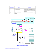
Hardware Block Diagram
 |
View all Intel RS25DB080 manuals
Add to My Manuals
Save this manual to your list of manuals |
Page 25 highlights
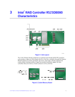
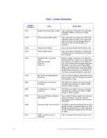
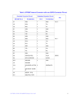
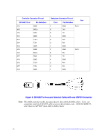
Jumper / Connector J5B1 J6A1 Type Board-to-board Connector for the memory board UART connector for the expander Description Provides an interface to the memory board that contains 1GB 667MHz DDR3 memory. The memory board can be connected to an optional Intel® RAID Smart Battery AXXRSBBU9. 4-pin connector Reserved for factory use. Figure 6. Hardware Block Diagram Intel® RAID Controller RS25DB080 Hardware User's Guide 15
-
 1
1 -
2
-
3
-
4
-
5
-
6
-
7
-
8
-
9
-
10
-
11
-
12
-
13
-
14
-
15
-
16
-
17
-
18
-
19
-
 20
20 -
 21
21 -
 22
22 -
 23
23 -
 24
24 -
 25
25 -
 26
26 -
 27
27 -
 28
28 -
 29
29 -
 30
30 -
31
-
32
-
33
-
34
-
35
-
36
-
37
-
38
-
39
-
40
-
41
-
42
-
43
-
44
-
45
-
46
-
47
-
48
-
49
-
50
-
51
-
52
-
53
-
54
 |
 |

Intel® RAID Controller RS25DB080 Hardware User’s Guide
15
Figure 6. Hardware Block Diagram
J5B1
Board-to-board Connector for
the memory board
Provides an interface to the memory board
that contains 1GB 667MHz DDR3 memory.
The memory board can be connected to an
optional Intel® RAID Smart Battery
AXXRSBBU9.
J6A1
UART connector for the
expander
4-pin connector Reserved for factory use.
Jumper /
Connector
Type
Description