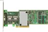
Intel RS25DB080 Hardware User Guide - Page 7
List of s - battery
 |
View all Intel RS25DB080 manuals
Add to My Manuals
Save this manual to your list of manuals |
Page 7 highlights
List of Figures Figure 1. Changing the Bracket 8 Figure 2. Installing the Intel® RAID Controller RS25DB080 9 Figure 3. Connecting Cable between the RAID Controller and Drives/Backplane 10 Figure 4. Card Layout...13 Figure 5. Cache Memory Board 13 Figure 6. Hardware Block Diagram 15 Figure 7. Intel® RAID Smart Battery AXXRSBBU9 17 Figure 8. Intel® RAID Controller RS25DB080 SAS/SATA Connectors 18 Figure 9. SFF8087 to Four-port Internal Cable with one SGPIO Connector 20 Figure 10. LED Header ...22 Figure 11. Individual PHY/Drive Fault Header 23 Figure 12. UART Connector...24 Intel® RAID Controller RS25DB080 Hardware User's Guide vii
-
 1
1 -
 2
2 -
 3
3 -
 4
4 -
 5
5 -
 6
6 -
 7
7 -
 8
8 -
 9
9 -
 10
10 -
 11
11 -
 12
12 -
13
-
14
-
15
-
16
-
17
-
18
-
19
-
20
-
21
-
22
-
23
-
24
-
25
-
26
-
27
-
28
-
29
-
30
-
31
-
32
-
33
-
34
-
35
-
36
-
37
-
38
-
39
-
40
-
41
-
42
-
43
-
44
-
45
-
46
-
47
-
48
-
49
-
50
-
51
-
52
-
53
-
54
 |
 |

Intel® RAID Controller RS25DB080 Hardware User’s Guide
vii
List of Figures
Figure 1. Changing the Bracket
.................................................................................................
8
Figure 2. Installing the Intel
®
RAID Controller RS25DB080
......................................................
9
Figure 3. Connecting Cable between the RAID Controller and Drives/Backplane
..................
10
Figure 4. Card Layout
..............................................................................................................
13
Figure 5. Cache Memory Board
..............................................................................................
13
Figure 6. Hardware Block Diagram
.........................................................................................
15
Figure 7. Intel
®
RAID Smart Battery AXXRSBBU9
.................................................................
17
Figure 8. Intel
®
RAID Controller RS25DB080 SAS/SATA Connectors
...................................
18
Figure 9. SFF8087 to Four-port Internal Cable with one SGPIO Connector
...........................
20
Figure 10. LED Header
...........................................................................................................
22
Figure 11. Individual PHY/Drive Fault Header
........................................................................
23
Figure 12. UART Connector
....................................................................................................
24