Intel RS2WG160 Hardware User Guide - Page 22
Jumper, Description, Sized Cache, FastPath, and Full Disk Encryption.
 |
View all Intel RS2WG160 manuals
Add to My Manuals
Save this manual to your list of manuals |
Page 22 highlights
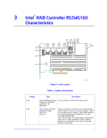
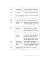
Jumper J1B3 J1C1 J1L1 J2B1 J2B2 J2D1 J3B1 J4A1 J4A2 J4A3 J4A4 J4B2 J5A2 J5B3 Type Description Premium Features Hardware Key header 2-pin header. Enables support for selected premium features, which include Snapshot, Super Sized Cache, FastPath, and Full Disk Encryption. IPMI-style I2C connector 3-pin connector. Supports SES (SCSI enclosure services) over I2C through an internal I2C backplane cable Remote Battery Backup 20-pin connector.Connects the intelligent Battery connector (on the back- Backup Unit remotely to the RAID controller. side of the controller) x4 SAS Ports 0-3 inter- SFF-8087 x4 internal mini SAS connector Con- nal connector nects the controller by cable to SAS/SATA drives. x4 SAS Ports 4-7 inter- SFF-8087 x4 internal mini SAS connector Con- nal connector nects the controller by cable to SAS/SATA drives. Standard edge card connector The RAID controller interfaces with the host system though a standard edge card. This interface provides power to the board and an I2C interface connected to the I2C bus for IPMI. x4 SAS Ports 8-11 inter- SFF-8087 x4 internal mini SAS connector Con- nal connector nects the controller by cable to SAS/SATA drives. Module CPLD 1x8-pin connector. Reserved for factory use. Activity LED header 2-pin connector. Connects to an LED that indicates activity on the drives connected to the controller. Global drive fault LED 2-pin connector. Connects to an LED that indicates header whether a drive is in a fault condition. LED Locate and Fault Indication header Ports 8-11 Ports 12-15 2x8-pin connector. Connects to an LED that indicates whether a drive is in a fault condition. There is one LED per port. When lit, each LED indicates the corresponding drive has failed or is in the unconfigured-bad state. The LEDs function in a direct-attach configuration (there are no SAS expanders). Direct attach is defined as a maximum of one drive connected directly to each port. x4 SAS Ports 12-15 internal connector SFF-8087 x4 internal mini SAS connector Connects the controller by cable to SAS/SATA drives. Write pending LED header 2-pin connector. Connects to an LED that indicates when the data in the cache has yet to be written to the storage devices. Used when the write-back feature is enabled. Universal Asynchronous 4-pin connector Reserved for factory use. Receiver/Transmitter (UART) debugging 12 Intel® RAID Controller RS2WG160 Hardware User's Guide
-
 1
1 -
2
-
3
-
4
-
5
-
6
-
7
-
8
-
9
-
10
-
11
-
12
-
13
-
14
-
15
-
16
-
 17
17 -
 18
18 -
 19
19 -
 20
20 -
 21
21 -
 22
22 -
 23
23 -
 24
24 -
 25
25 -
 26
26 -
 27
27 -
28
-
29
-
30
-
31
-
32
-
33
-
34
-
35
-
36
-
37
-
38
-
39
-
40
-
41
-
42
-
43
-
44
-
45
-
46
-
47
-
48
-
49
-
50
-
51
-
52
 |
 |
