Intel RS2WG160 Hardware User Guide - Page 26
LED Placement and Function, SAS/SATA Connectors
 |
View all Intel RS2WG160 manuals
Add to My Manuals
Save this manual to your list of manuals |
Page 26 highlights
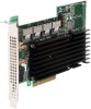
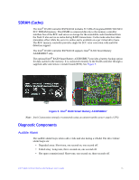
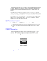
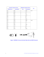
The drive failure tones repeat until the problem is corrected, or until the alarm is silenced or disabled. The alarm can be silenced or disabled on the controller's properties page in the BIOS Console or by using the failed drive options pane in the Intel® RAID Web Console 2. Silencing the alarm is temporary. If the cause of failure still exists or if an additional failure is detected, then the alarm sounds again when the system is rebooted. Disabling the alarm is persistent across errors and reboots. When the alarm is disabled, a failure does not cause it to sound until it is re-enabled. The rebuild alarm tone functions differently. It remains ON during the rebuild. After the rebuild completes, an alarm with a different tone sounds to signal that the rebuild is complete. This is a one-time, non-repeating tone. LED Placement and Function The Intel® RAID Controller RS2WG160 contains the following LEDs: • One surface-mounted heartbeat LED (Green Color) to indicate SAS2108 activity. • Another surface-mounted system error LED (Amber Color) to indicate a board error. SAS/SATA Connectors The Intel® Integrated RAID controller RS2WG160 provides four internal SFF8087 SAS/SATA signal connectors. Each SFF8087 connector provides support for four SAS/SATA ports. The sideband signals are configured to adhere to the SFF-8485 Specifications for SGPIO support. Internal connector Figure 6. Intel® RAID Controller RS2WG160 SAS/SATA Connectors 16 Intel® RAID Controller RS2WG160 Hardware User's Guide
-
 1
1 -
2
-
3
-
4
-
5
-
6
-
7
-
8
-
9
-
10
-
11
-
12
-
13
-
14
-
15
-
16
-
17
-
18
-
19
-
20
-
 21
21 -
 22
22 -
 23
23 -
 24
24 -
 25
25 -
 26
26 -
 27
27 -
 28
28 -
 29
29 -
 30
30 -
 31
31 -
32
-
33
-
34
-
35
-
36
-
37
-
38
-
39
-
40
-
41
-
42
-
43
-
44
-
45
-
46
-
47
-
48
-
49
-
50
-
51
-
52
 |
 |
