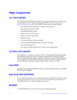
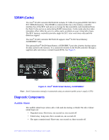
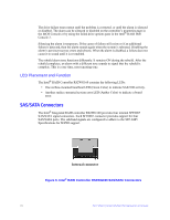
Intel RS2WG160 Hardware User Guide - Page 29
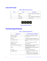
BBU Connector Pin-out
 |
View all Intel RS2WG160 manuals
Add to My Manuals
Save this manual to your list of manuals |
Page 29 highlights
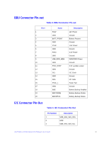
BBU Connector Pin-out Table 3. BBU Connector Pin-out Pin # 1 2 3 4 5 6 7 8 9 10 11 12 13 14 15 16 17 18 19 20 Name P12V GND BATT_PRSNT GND P1V8 GND P3V3 GND VBB_DDR_MEM GND P3V3_STBY GND SCL GND SDA PFAIL_L GND BBE BBSTROBE BBSTATUS Description 12V Power Ground Battery Present Ground 1.8V Power Ground 3.3V Power Ground DDR/DDRII Power Ground 3.3V auxiliary power Ground I2C Clock Ground I2C Data Power Fail Ground Battery Backup Enabled Battery Backup Strobe Battery Backup Status I2C Connector Pin-Out Table 4. I2C Connector Pin-Out Pin Number 1 2 3 Description SMB_SAS_SES_SDA GND SMB_SAS_SES_SCL Intel® RAID Controller RS2WG160 Hardware User's Guide 19
-
 1
1 -
2
-
3
-
4
-
5
-
6
-
7
-
8
-
9
-
10
-
11
-
12
-
13
-
14
-
15
-
16
-
17
-
18
-
19
-
20
-
21
-
22
-
23
-
 24
24 -
 25
25 -
 26
26 -
 27
27 -
 28
28 -
 29
29 -
 30
30 -
 31
31 -
 32
32 -
 33
33 -
 34
34 -
35
-
36
-
37
-
38
-
39
-
40
-
41
-
42
-
43
-
44
-
45
-
46
-
47
-
48
-
49
-
50
-
51
-
52
 |
 |

Intel® RAID Controller RS2WG160 Hardware User’s Guide
19
BBU Connector Pin-out
Table 3. BBU Connector Pin-out
I2C Connector Pin-Out
Table 4. I2C Connector Pin-Out
Pin #
Name
Description
1
P12V
12V Power
2
GND
Ground
3
BATT_PRSNT
Battery Present
4
GND
Ground
5
P1V8
1.8V Power
6
GND
Ground
7
P3V3
3.3V Power
8
GND
Ground
9
VBB_DDR_MEM
DDR/DDRII Power
10
GND
Ground
11
P3V3_STBY
3.3V auxiliary power
12
GND
Ground
13
SCL
I2C Clock
14
GND
Ground
15
SDA
I2C Data
16
PFAIL_L
Power Fail
17
GND
Ground
18
BBE
Battery Backup Enabled
19
BBSTROBE
Battery Backup Strobe
20
BBSTATUS
Battery Backup Status
Pin Number
Description
1
SMB_SAS_SES_SDA
2
GND
3
SMB_SAS_SES_SCL