Intel S3420GPLC Product Specification
Intel S3420GPLC - Server Board Motherboard Manual
 |
UPC - 735858211819
View all Intel S3420GPLC manuals
Add to My Manuals
Save this manual to your list of manuals |
Intel S3420GPLC manual content summary:
- Intel S3420GPLC | Product Specification - Page 1
Intel® Server Board S3420GP Technical Product Specification Intel order number E65697-010 Revision 2.4 January, 2011 Enterprise Platforms and Services Division - Marketing - Intel S3420GPLC | Product Specification - Page 2
Revision History Intel® Server Board S3420GP TPS Date Feb. Intel® Server Board S3420GPV details. Updated processor name. Corrected the typo. Corrected the typo, updated processor name and remove CCC certification marking information. Corrected the typo. Corrected the typo. Added RDIMM support - Intel S3420GPLC | Product Specification - Page 3
be held responsible if components fail or the server board does not operate correctly when used outside any of their published operating or non-operating limits. Intel, Pentium, Itanium, and Xeon are trademarks or registered trademarks of Intel Corporation. *Other brands and names may be claimed as - Intel S3420GPLC | Product Specification - Page 4
Layout 6 2.2.2 Intel® Server Board S3420GP Mechanical Drawings 8 2.2.3 Server Board Rear I/O Layout 14 3. Functional Architecture...15 3.1 Processor Sub-System 17 3.1.1 Intel® Xeon® Processor 3400 Series 17 3.1.2 Intel® CoreTM Processor i3-500 Series and Intel® Pentium® Processor G6950 - Intel S3420GPLC | Product Specification - Page 5
37 4.2.3 Media Redirection 38 4.2.4 Web Services for Management (WS-MAN 38 4.2.5 Local Directory Authentication Protocol (LDAP 39 4.2.6 Embedded Webserver 39 4.3 Management Engine (ME 39 5. Server Management Capability for Intel® Server Board S3420GPV 40 5.1 Super I/O ...40 - Intel S3420GPLC | Product Specification - Page 6
Jumper 94 9. Intel® Light Guided Diagnostics 95 9.1 System Status LED (For the Intel® Server Board S3420GPLX and S3420GPLC Intel® Server Board S3420GP Design Specifications 97 10.2 Board-level Calculated MTBF 97 10.3 Server Board Power Requirements 98 10.3.1 Processor Power Support - Intel S3420GPLC | Product Specification - Page 7
Intel® Server Board S3420GP TPS Table of Contents 10.4.10 Timing Requirements 101 10.4.11 Residual Appendix C: POST Code Diagnostic LED Decoder 119 Appendix D: POST Code Errors 123 Appendix E: Supported Intel® Server Chassis 128 Glossary ...129 Reference Documents...132 Revision 2.4 vii - Intel S3420GPLC | Product Specification - Page 8
List of Figures Intel® Server Board S3420GP TPS List of Figures Figure 1. Intel® Server Board S3420GPLX Picture 5 Figure 2. Intel® Server Board S3420GP Layout 6 Figure 3. Intel® Server Board S3420GP - Key Connector and LED Indicator IDENTIFICATION 8 Figure 4. Intel® Server Board S3420GP - Hole - Intel S3420GPLC | Product Specification - Page 9
Intel® Server Board S3420GP TPS List of Figures Figure 40. Power Distribution Block Diagram 98 Figure 41. Output Voltage Timing 102 Figure 42. Turn On/Off Timing (Power Supply Signals 103 Figure 43. Diagnostic LED Placement Diagram 119 Revision 2.4 ix Intel order number E65697-010 - Intel S3420GPLC | Product Specification - Page 10
Tables Intel® Server Board S3420GP TPS List of Tables Table 1. Intel® Server Board Display Fields 53 Table 20. Setup Utility - Processor Configuration Screen Fields 54 Table 21. Setup Fields 62 Table 26. Setup Utility - System Acoustic and Performance Configuration Screen Fields ........ - Intel S3420GPLC | Product Specification - Page 11
Intel® Server Board S3420GP TPS List of Tables Table 40. SSI Processor Power Connector Pin-out (J9C1 77 Table 41. Intel® RMM3 Connector Table 72. Over-voltage Protection (OVP) Limits 104 Table 73. Integrated BMC Core Sensors 115 Table 74. POST Progress Code LED Example 119 Table 75. Diagnostic - Intel S3420GPLC | Product Specification - Page 12
List of Tables Intel® Server Board S3420GP TPS xii Revision 2.4 Intel order number E65697-010 - Intel S3420GPLC | Product Specification - Page 13
Appendix C - POST Code Diagnostic LED Decoder Appendix D - POST Code Errors Appendix E - Supported Intel® Server Chassis Glossary Reference Documents 1.2 Server Board Use Disclaimer Intel Corporation server boards contain a number of high-density VLSI and power delivery components that need - Intel S3420GPLC | Product Specification - Page 14
S3420GPLC, and S3420GPV. 2.1 Intel® Server Board S3420GP Feature Set Table 1. Intel® Server Board S3420GP Feature Set Feature Processor Memory Chipset I/O Description Support for one Xeon® Processor 3400 Series or Intel® CoreTM Processor i3-500 Series or Intel® Pentium® Processor G6950 in FC-LGA - Intel S3420GPLC | Product Specification - Page 15
Intel® Server Board S3420GP TPS Overview Feature Add-in PCI Card, PCI Express* Card System Fan Support Video Onboard Hard Drive RAID Support LAN Intel® Server connector. Five 4-pin fan headers supporting four system fans and one processor. Intel® Server Board S3420GPLX/ S3420GPLC Onboard - Intel S3420GPLC | Product Specification - Page 16
Feature Server Management Intel® Server Board S3420GP TPS Description Intel® Server Board S3420GPLX/S3420GPLC: Onboard LLC Pilot II Controller (iBMC) Integrated Baseboard Management Controller (Integrated BMC), IPMI 2.0 compliant Integrated 2D video controller on PCI-E x1 Intel® Server Board - Intel S3420GPLC | Product Specification - Page 17
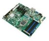
Intel® Server Board S3420GP TPS 2.2 Server Board Layout Overview Figure 1. Intel® Server Board S3420GPLX Picture Revision 2.4 5 Intel order number E65697-010 - Intel S3420GPLC | Product Specification - Page 18
Overview Intel® Server Board S3420GP TPS 2.2.1 Server Board Connector and Component Layout The following figure shows the board layout of the server board. Each connector and major component is identified by a number or letter, and Table 2 provides the description. A BCD E F G H I JK L M N - Intel S3420GPLC | Product Specification - Page 19
Intel® Server Board S3420GP TPS Overview Table 2. Major Board Components Description Description A Slot 1, 32 Mbit/33 MHz PCI Q System FAN2 and System FAN 3 B Slot 2, PCI Express* Gen1 x1 (x4 connector) (Intel Server Board S3420GPLX only) R CPU connector C Intel RMM3 Connector(Intel Server - Intel S3420GPLC | Product Specification - Page 20
Overview 2.2.2 Intel® Server Board S3420GP TPS Intel® Server Board S3420GP Mechanical Drawings Figure 3. Intel® Server Board S3420GP - Key Connector and LED Indicator IDENTIFICATION 8 Revision 2.4 Intel order number E65697-010 - Intel S3420GPLC | Product Specification - Page 21
Intel® Server Board S3420GP TPS Overview Figure 4. Intel® Server Board S3420GP - Hole and Component Positions Revision 2.4 9 Intel order number E65697-010 - Intel S3420GPLC | Product Specification - Page 22
Overview Intel® Server Board S3420GP TPS Figure 5. Intel® Server Board S3420GP - Major Connector Pin Location (1 of 2) 10 Revision 2.4 Intel order number E65697-010 - Intel S3420GPLC | Product Specification - Page 23
Intel® Server Board S3420GP TPS Overview Figure 6. Intel® Server Board S3420GP -Major Connector Pin Location (2 of 2) Revision 2.4 11 Intel order number E65697-010 - Intel S3420GPLC | Product Specification - Page 24
Overview Intel® Server Board S3420GP TPS Figure 7. Intel® Server Board S3420GP - Primary Side Keepout Zone 12 Revision 2.4 Intel order number E65697-010 - Intel S3420GPLC | Product Specification - Page 25
Intel® Server Board S3420GP TPS Overview Figure 8. Intel® Server Board S3420GP - Secondary Side Keepout Zone Revision 2.4 13 Intel order number E65697-010 - Intel S3420GPLC | Product Specification - Page 26
® Server Board S3420GP TPS 2.2.3 Server Board Rear I/O Layout The following figure shows the layout of the rear I/O components for the server board. A Serial Port A B Video C NIC Port 1 (1 Gb) and Dual USB Port Connector D NIC port 2 (1 Gb) and Dual USB Port Connector Figure 9. Intel® Server - Intel S3420GPLC | Product Specification - Page 27
The architecture and design of the Intel® Server Board S3420GP is based on the Intel® 3420 Chipset. The chipset is designed for systems based on the Intel® Xeon® Processor 3400 Series or Intel® CoreTM i3-500 Desktop Processor Series or Intel® Pentium® Processor Processor G6950in the FC-LGA 1156 - Intel S3420GPLC | Product Specification - Page 28
Functional Architecture Intel® Server Board S3420GP TPS Figure 11. Intel® Server Board S3420GP Functional Block Diagram From S3420GPLC 16 Revision 2.4 Intel order number E65697-010 - Intel S3420GPLC | Product Specification - Page 29
-System The Intel® Server Board S3420GP supports the following processor: Intel® Xeon® Processor 3400 series Intel® CoreTM Processor i3-500 Desktop series Intel® Pentium® Processor G6950 The Intel® Xeon® 3400 Processor Series are made up of multi-core processors based on the 45 nm processor - Intel S3420GPLC | Product Specification - Page 30
be supported with the Intel® Core® i3-500 Desktop Processor Series and Intel® Pentium® Processor G6950. RAS (Reliability, Availability, and Serviceability) is not supported on the Intel® Server Board S3420GP. 3.2.1 Memory Sizing and Configuration The Intel® Server Board S3420GP supports various - Intel S3420GPLC | Product Specification - Page 31
Intel® Server Board S3420GP TPS Functional Architecture S3420GP supports: DIMM sizes of 1 GB, 2 GB, 4 GB, and 8 GB. beeping and then continues POST. If all of the memory fails HW Memory BIST, the system acts as if no memory is available, beeping and halting with the POST Diagnostic LED code - Intel S3420GPLC | Product Specification - Page 32
or greater than 4 GB. For the operating system, the reclaimed memory is recoverable only if the PAE feature in the processor is supported and enabled. Most operating systems support this feature. For details, see the relevant operating system manuals. 20 Revision 2.4 Intel order number E65697-010 - Intel S3420GPLC | Product Specification - Page 33
can support a maximum of six DIMM sockets. 4. The Intel® Xeon® Processor 3400 Series on the Intel® Server Board S3420GP is populated on the processor socket processor socket to which they belong. For example, DIMM_A1 is the first slot on channel A. 3.2.4.3 Memory Upgrade Rules Upgrading the system - Intel S3420GPLC | Product Specification - Page 34
or Intel® Pentium® Processor G6950 only support UDIMMs. 5. RDIMM and UDIMM CAN NOT be mixed. 6. The minimal memory set is {DIMMA1}. 7. DDR3 DIMMs on adjacent slots on the same channel do not need to be identical. Each socket supports a maximum of six slots. Standard Intel® server boards and systems - Intel S3420GPLC | Product Specification - Page 35
Maximum configuration Intel® Server Board S3420GP has the following limitations on UDIMM. Not support 800MHz ECC UDIMMs No support for LV DIMMs 256Mb technology, x4 DRAM on UDIMM and quad rank UDIMM are NOT supported x16 DRAM is not supported on combo routing All channels in a system will - Intel S3420GPLC | Product Specification - Page 36
Note : 1066MHz or 1333MHz RDIMMs run at 800MHz. 3.3 Intel® 3420 Chipset PCH The Intel® 3420 Chipset component is the Platform Controller Hub (PCH). The PCH is designed for use with Intel® processor in a UP server platform. The role of the PCH in Intel® Server Board S3420GP is to manage the flow of - Intel S3420GPLC | Product Specification - Page 37
system Intel® 3420 Chipset PCH provides extensive I/O support. 3.4.1 PCI Express Interface Two different PCI-E configurations on single board are dependent on different board SKUs: Intel® Server to ensure all existing applications and drivers operate unchanged. The PCI Express* configuration - Intel S3420GPLC | Product Specification - Page 38
Functional Architecture Intel® Server Board S3420GP TPS 3.4.2 Serial ATA Support The Intel® 3420 Chipset has two integrated SATA host controllers that support independent DMA operation on up to six ports and supports data transfer rates of up to 3.0 GB/s (300 MB/s). The SATA controller contains - Intel S3420GPLC | Product Specification - Page 39
Intel® Server Board S3420GP TPS Functional Architecture During the pre-boot phase, the BIOS automatically supports the hot addition each USB device plugged into the system as they were all just "hot added". Boards and systems based on the Intel® Server Board S3420GPLX or S3420GPLC are designed - Intel S3420GPLC | Product Specification - Page 40
Intel® Server Board S3420GP TPS The ServerEngines* LLC Pilot II Integrated BMC is provided by an embedded ARM9 controller and associated peripheral functionality that is required for IPMI-based server ARM9 Processor Memory Management Unit (MMU) Two 10/100 Ethernet Controllers with NC-SI support - Intel S3420GPLC | Product Specification - Page 41
host. For these channels, support can be enabled for IPMI-over-LAN and DHCP. For security reasons, embedded LAN channels have the following default settings: IP Address: Static All users disabled 3.6.2 Optional RMM3 Advanced Management Board Intel® Server Board S3420GPLX provides one RMM3 - Intel S3420GPLC | Product Specification - Page 42
Functional Architecture Intel® Server Board S3420GP TPS Give the customer the option to add a dedicated management 100 Mbit LAN interface to the product. Provide additional flash space, enabling the Advanced Management functions to support WS-MAN and CIMON. Table 9. Optional RMM3 Advanced - Intel S3420GPLC | Product Specification - Page 43
Intel® Server Board S3420GP TPS Functional Architecture 3.6.6 Wake-up Control The super I/O contains functionality that allows various events to power on and power off the system. 3.7 Video Support 3.7.1 Intel® Server Board S3420GPLX and Intel® Server Board S3420GPLC The server board - Intel S3420GPLC | Product Specification - Page 44
Functional Architecture Intel® Server Board S3420GP TPS 2D Mode Resolution 8 bpp 1440x900 Supported 60 2D Video Mode Support (Color Bit) 16 bpp 24 bpp Supported 60 Supported 60 32 bpp N/A N/A 1600x1200 Supported Supported N/A N/A 60, 65, 70, 75, 60, 65, 70 N/A N/A 85 (Hz) Monitor - Intel S3420GPLC | Product Specification - Page 45
Intel® Server Board S3420GP TPS Functional Architecture 3.8 Network Interface Controller (NIC) The Intel® Server Board S3420GPLX, S3420GPLC and S3420GPV support two network interfaces, One is provided from the onboard Intel® 82574L GbE PCI Express network controller; the other is the onboard Intel - Intel S3420GPLC | Product Specification - Page 46
support for implementation of Intel® Virtualization Technology with Directed I/O (Intel® VT-d). Intel VT-d Technology consists of technology components that support the virtualization of platforms based on Intel® Architecture Processor. Intel VT-d Technology enables multiple operating systems - Intel S3420GPLC | Product Specification - Page 47
for The Intel® Server Board S3420GPLX and Intel® Server Board S3420GPLC. The platform management subsystem is based on the Integrated BMC features of the ServerEngines* Pilot II. The onboard platform management subsystem consists of communication buses, sensors, system BIOS, and server management - Intel S3420GPLC | Product Specification - Page 48
Platform Management Intel® Server Board S3420GP TPS Field replaceable unit (FRU) inventory device functionality: The Integrated BMC supports access to system FRU devices using IPMI FRU commands. System event log (SEL) device functionality: The Integrated BMC supports and provides access to a - Intel S3420GPLC | Product Specification - Page 49
Intel® Server Board S3420GP TPS Platform Management Power unit management: Support for power unit sensor. The Integrated Baseboard Management redirection is available after video is initialized by the system BIOS. The KVM video resolution and refresh rates will always match the values set - Intel S3420GPLC | Product Specification - Page 50
Platform Management Intel® Server Board S3420GP TPS 4.2.2.3 Availability Up to two remote KVM sessions are supported. The default inactivity timeout is 30 minutes; however, this can be changed through the embedded web server. Remote KVM activation does not disable the local system keyboard, - Intel S3420GPLC | Product Specification - Page 51
Intel® Server Board S3420GP TPS Platform Management 4.2.5 Local Directory Authentication Protocol (LDAP) The Integrated BMC firmware supports the Local Directory Authentication Protocol (LDAP) protocol for user authentication. Note: IPMI users/passwords and sessions are not supported over LDAP. - Intel S3420GPLC | Product Specification - Page 52
Management Capability for Intel® Server Board S3420GPV Intel® Server Board S3420GP TPS 5. Server Management Capability for Intel® Server Board S3420GPV 5.1 Super I/O 5.1.1 Key Features of Super I/O The W83627DHG-P is from the Nuvoton's Super I/O product line. This family features the LPC - Intel S3420GPLC | Product Specification - Page 53
Intel® Server Board S3420GP TPS Server Management Capability for Intel® Server Board S3420GPV Main Advance d Security Server Management Hardware monitor Boot Options Real-time Temperature and Voltage Status Fan Controller Auto/Manual CPU Fan Altitude Board Fan Altitude 300m/900m/1500m - Intel S3420GPLC | Product Specification - Page 54
Management Capability for Intel® Server Board S3420GPV Intel® Server Board S3420GP TPS Note: The two options of Hysteresis and Default Fan PWM apply to all the four fans 5.1.3 Fan controller (Manual) Fan controller (Manual) allows the user to configure Fan speed control manually. To access this - Intel S3420GPLC | Product Specification - Page 55
Intel® Server Board S3420GP TPS Server Management Capability for Intel® Server Celsius/4 Degree Celsius [ 40%/60 %/80%/ 100%] System Fan Hysteresis Default Fan PWM [2 Degree Celsius/3 Degree Figure 16. Setup Utility - Fan controller (Manual) Display Table 14. Setup Utility - Hardware Monitor - Intel S3420GPLC | Product Specification - Page 56
Management Capability for Intel® Server Board S3420GPV Intel® Server Board S3420GP TPS Setup Item CPU Fan Altitude System Fan Altitude Hysteresis Default Fan PWM Options 300m/900m/1500m/3000m 300m/900m/1500m/3000m 2 Degree Celsius 3 Degree Celsius 4 Degree Celsius 40% 60% 80% 100% - Intel S3420GPLC | Product Specification - Page 57
software can use the SMBIOS table for system management purpose. 5.3 Event log and Viewer 5.3.1 Event Log Viewer in Setup On Intel® Server Board S3420GPLX and Intel® Server Board S3420GPLC, there is a dedicated utility to view the event log. There is no IPMI support - the way to view the event - Intel S3420GPLC | Product Specification - Page 58
Management Capability for Intel® Server Board S3420GPV Intel® Server Board S3420GP TPS No. Error Manager Event Info Time 005 M-BIT MEM ECC Error CPU0 Ch 0 Dimm0 10/15/ a scroll bar to allow end-users to view the logs from top to bottom. 46 Revision 2.4 Intel order number E65697-010 - Intel S3420GPLC | Product Specification - Page 59
Intel® Server Board S3420GP TPS BIOS User Interface system configuration, the summary and diagnostic screen displays. The diagnostic screen displays the following information: BIOS ID Platform name Total memory detected (Total size of all installed DDR3 DIMMs) Processor information (Intel - Intel S3420GPLC | Product Specification - Page 60
Intel® server board BIOS is only available in English. Console Redirection - The BIOS Setup is functional through console redirection over various terminal emulation standards. This may limit some functionality for compatibility (for example, color usage or some keys or key sequences or support - Intel S3420GPLC | Product Specification - Page 61
Intel® Server Board S3420GP TPS BIOS User Interface feature's value may or may not be changed. If is selected and the key is pressed, the setup is exited and the BIOS returns to the main System Options Menu screen. The up arrow is used to select the previous value in a pick list, or the - Intel S3420GPLC | Product Specification - Page 62
BIOS User Interface Intel® Server Board S3420GP TPS Key Option Save and Exit Description Pressing is changed (except Date and Time), the system requires a save and reboot to take place. Pressing discards the changes and boots the system according to the boot order set from the - Intel S3420GPLC | Product Specification - Page 63
Intel® Server Board S3420GP TPS BIOS User Interface Main Advance d Security Server Management Boot Options Boot Manager Logged in as Platform ID System BIOS Version SXXXX.86B.xx.yy.zzzz Build Date - Intel S3420GPLC | Product Specification - Page 64
BIOS User Interface Intel® Server Board S3420GP TPS Setup Item Size Quiet Boot Options Enabled Disabled Help Text [Enabled] - Display the logo screen during POST. Comments Information only. Displays the total physical memory installed in the system, in MB or GB. The term physical memory - Intel S3420GPLC | Product Specification - Page 65
Intel® Server Board S3420GP TPS BIOS User Interface Main Advance d Security Server Management Boot Options Boot Manager ► Processor Configuration ► Memory Configuration ► Mass Storage Controller Configuration ► Serial Port Configuration ► USB Configuration ► PCI Configuration ► System - Intel S3420GPLC | Product Specification - Page 66
BIOS User Interface Intel® Server Board S3420GP TPS Advanced Processor Configuration Processor Socket Processor ID Processor Frequency Microcode Revision L1 Cache RAM L2 Cache RAM L3 Cache RAM Processor 1 Version CPU 1 Size of Cache Size of Cache Size of Cache - Intel S3420GPLC | Product Specification - Page 67
feature. Enable 1, 2 or All cores of installed processor packages. Information only. Current speed that the QPI Link is using. Information only. Current frequency that the QPI Link is using. This option is only visible if all processor in the system support Intel® Turbo Boost Technology. Execute - Intel S3420GPLC | Product Specification - Page 68
Interface Intel® Server Board S3420GP TPS Setup Item Adjacent Cache Line Prefetch Options Enabled Disabled Help Text [Enabled] - Cache lines are fetched in pairs (even line + odd line). [Disabled] - Only the current cache line required is fetched. Note: Modifying this setting may affect system - Intel S3420GPLC | Product Specification - Page 69
Intel® Server Board S3420GP TPS BIOS User Interface Setup Item Effective Memory Current Configuration Comments Information only. The amount of memory available to the operating system in MB or GB. The Effective Memory is the difference between the Total Physical Memory and the sum of all memory - Intel S3420GPLC | Product Specification - Page 70
BIOS User Interface Intel® Server Board S3420GP TPS Advanced Mass Storage Controller Configuration Intel® Entry SAS RAID Module Configure Intel® Entry SAS RAID Module Onboard SATA Controller Configure SATA Mode Enabled/Disabled LSI ® Integrated RAID/Intel® ESRTII Enabled/Disabled ENHANCED/ - Intel S3420GPLC | Product Specification - Page 71
Intel® Server Board S3420GP TPS BIOS User Interface Setup Item SATA Port 0 SATA Port 1 SATA Port 2 SATA Port 3 SATA Port 4 SATA Port 5 Options < 3F8h 2F8h 3E8h 2E8h Help Text Enable or Disable Serial port A. Select Serial port A base I/O address. Revision 2.4 59 Intel order number E65697-010 - Intel S3420GPLC | Product Specification - Page 72
BIOS User Interface Intel® Server Board S3420GP TPS Setup Item IRQ Serial B Enable Address IRQ Options 3 4 Enabled Disabled 3F8h USB Configuration Detected USB Devices USB Controller Legacy USB Support Port 60/64 Emulation Make USB Devices Non-Bootable Enabled - Intel S3420GPLC | Product Specification - Page 73
Intel® Server Board S3420GP TPS BIOS User Interface Table 24. Setup Utility - USB Controller Configuration Screen Fields Setup Item Detected USB Devices USB Controller Legacy USB Support more than eight devices are installed in the system, the USB Devices Enabled shows the correct count, - Intel S3420GPLC | Product Specification - Page 74
Enabled/Disabled Enabled/Disabled Intel® Server Board S3420GP TPS Figure 26. Setup Utility - PCI Configuration If [Disabled] is selected, NIC2 cannot be used to boot or wake the system. When disabled, the system requires an add-in video card for the video to be seen. Note: This - Intel S3420GPLC | Product Specification - Page 75
Intel® Server Board S3420GP TPS BIOS User Interface Setup Item Onboard NIC iSCSI ROM NIC 1 MAC Address NIC only. If the user selects OLTT, the BIOS overrides that selection if the system can support CLTT. OLTT is configured only when UDIMMs without Thermal Sensors are installed. Revision 2.4 63 - Intel S3420GPLC | Product Specification - Page 76
Intel® Server Board S3420GP TPS system cooling before attempting to throttle memory. [Acoustic] - The system will favor using throttling of memory over boosting fans to cool the system (TPM) security is NOT supported on the Intel® Server S3420GP board. To access this screen from the Main - Intel S3420GPLC | Product Specification - Page 77
Intel® Server Board S3420GP TPS BIOS User Interface Setup Item User Password Status Set Administrator power button and reset button on the system's front panel. If [Enabled] is selected, power and reset must be controlled via a system management interface. Comments Information only. Indicates - Intel S3420GPLC | Product Specification - Page 78
BIOS User Interface Intel® Server Board S3420GP TPS Main Advance d Security Server Management Boot Options Boot Manager Assert NMI on SERR Assert NMI on PERR Resume on AC Power Loss Clear System Event Log Enabled/Disabled Enabled/Disabled Stay Off/Last state/Reset Enabled/Disabled FRB-2 - Intel S3420GPLC | Product Specification - Page 79
Intel® Server Board S3420GP TPS BIOS User Interface Setup Item O/S Boot Watchdog Timer O/S Boot Watchdog Timer Policy O/S Boot Watchdog Timer Timeout Plug & Play BMC Detection ACPI 1.0 Support Console Redirection System Information Options Enabled Disabled Power Off Reset 5 minutes 10 minutes 15 - Intel S3420GPLC | Product Specification - Page 80
BIOS User Interface Intel® Server Board S3420GP TPS Table 29. Setup Utility - Console Redirection Configuration serial port is hidden from the legacy OS. 6.3.2.5 Server Management System Information Screen The Server Management System Information screen allows the user to view part numbers, - Intel S3420GPLC | Product Specification - Page 81
Intel® Server Board S3420GP TPS System Information Board Part Number Board Serial Number System Part Number System Serial Number Chassis Part Number Chassis Serial Number BMC Firmware Revision HSC Firmware Revision ME Firmware Revision SDR Revision UUID Server Management BIOS User Interface - Intel S3420GPLC | Product Specification - Page 82
BIOS User Interface Intel® Server Board S3420GP TPS Main Advance d Security Server Management Boot Options Boot Manager System Boot Timeout Boot Option #1 Boot Option #2 Boot Option #x Hard Disk - Intel S3420GPLC | Product Specification - Page 83
Intel® Server Board S3420GP TPS BIOS User Interface Setup Item BEV Device Order deleted, you can restore it by setting CMOS defaults (F9). If all types of bootable devices are installed in the system, the default boot order is: 1. CD/DVD-ROM 2. Floppy Disk Drive 3. Hard Disk Drive 4. PXE Network - Intel S3420GPLC | Product Specification - Page 84
BIOS User Interface Intel® Server Board S3420GP TPS Table 32. Setup Utility - Delete Boot Option Fields Setup Legacy devices for this Device group. Help Text Set system boot order by selecting the boot option for this position. Set system boot order by selecting the boot option for this position - Intel S3420GPLC | Product Specification - Page 85
Intel® Server Board S3420GP TPS BIOS User Interface Table 34. Setup Utility - CDROM Order Fields Setup Item CDROM #1 CDROM #2 Options Available Legacy devices for this Device group. Available Legacy devices for this Device group. Help Text Set system boot order by selecting the boot option for - Intel S3420GPLC | Product Specification - Page 86
BIOS User Interface Intel® Server Board S3420GP TPS Table 36. Setup Utility - Network Device Order Fields Setup Item Network Device #1 Network Device #2 Options Available Legacy devices for this Device group. Available Legacy devices for this Device group. Help Text Set system boot order by - Intel S3420GPLC | Product Specification - Page 87
Intel® Server Board S3420GP TPS BIOS User Interface IPMI command (set System Boot options command) Int15 AX=DA209 Choosing Load User Defaults from the Exit page of the BIOS Setup loads user set defaults instead of the - Intel S3420GPLC | Product Specification - Page 88
Intel® Server Board S3420GP TPS 7. Connector/Header Locations and Pin-outs 7.1 Board Connector Information The following section provides detailed information regarding all connectors, headers, and jumpers on the server 6 Intel® RMM3 1 50-pin PCI 1 Express* Connector CPU Fan 1 System Fans - Intel S3420GPLC | Product Specification - Page 89
40. SSI Processor Power Connector Pin-out System Management Headers 7.3.1 Intel® Remote Management Module 3 (Intel® RMM3) Connector A 34-pin Intel® RMM 3 connector (J2C1) is included on the server board to support the optional Intel® Remote Management Module 3. This server board does not support - Intel S3420GPLC | Product Specification - Page 90
Connector/Header Locations and Pin-outs Intel® Server Board S3420GP TPS Table 41. Intel® RMM3 Connector Pin-out (J2C1) Pin Signal Name 1 P3V3_AUX 3 P3V3_AUX ) Pin Signal Name 1 SMB_HSBP_5V_DAT 2 GND 3 SMB_HSBP_5V_CLK 4 FM_HSBP_ADD_C2 78 Revision 2.4 Intel order number E65697-010 - Intel S3420GPLC | Product Specification - Page 91
Intel® Server Board S3420GP TPS Connector/Header Locations and Pin-outs 7.3.4 SGPIO Header Table 44. supported functionality of each control panel feature. Note: Control panel features are also routed through the bridge board connector at location J1C1 as is implemented in Intel® Server Systems - Intel S3420GPLC | Product Specification - Page 92
of the reset button. 7.4.3 NMI Button The Intel® S3420GP Server Board family BIOS does not support the NMI button. 7.4.4 System Status Indicator LED The Intel® Server Board S3420GP that uses the Intel® Xeon® Processor 3400 Series has a system status indicator LED on the front panel. This - Intel S3420GPLC | Product Specification - Page 93
Intel® Server Board S3420GP TPS Connector/Header Locations and Pin-outs Color State Green ~1 Hz blink Criticality Degraded Description System to the Integrated BMC to provide the contribution to the system status LED. 2. Support for upper non-critical limit is not provided in the default - Intel S3420GPLC | Product Specification - Page 94
Connector/Header Locations and Pin-outs Intel® Server Board S3420GP TPS Pin Signal Name 3 V_IO_B_CONN 4 TP_VID_CONN_B4 5 GND 6 GND 7 GND 8 GND 9 TP_VID_CONN_B9 10 GND 11 TP_VID_CONN_B11 12 V_IO_DDCDAT 13 V_IO_HSYNC_CONN 14 V_IO_VSYNC_CONN 15 V_IO_DDCCLK Description Blue - Intel S3420GPLC | Product Specification - Page 95
Intel® Server Board S3420GP TPS Connector/Header Locations and Pin-outs Pin 21 Signal Name LED_NIC1_2 pair Ground 7.5.4 50-pin PCI Express* Connector The Intel® Server Board S3420GPLX provides one 50-pin PCI Express* connector for Intel® SAS Entry RAID Module AXX4SASMOD. The pin configuration - Intel S3420GPLC | Product Specification - Page 96
Intel® Server Board S3420GP TPS Pin Signal Name 45 P3V3 47 P3V3 49 P3V3 Pin 46 48 50 P3V3 P3V3 P3V3 Signal Name 7.5.5 Serial Port Connectors The server connector on the server board (J1E1, J1D1) provides an option to support an additional USB port, each connector supporting two USB ports. - Intel S3420GPLC | Product Specification - Page 97
Intel® Server Board S3420GP TPS Connector/Header Locations and Pin-outs Pin Signal Name 3 USB_ICH_P4N_CONN 2 USB_N 3 USB_P 4 GND One 2x5 connectors (J3F2) on the server board provides an option to support an Intel® Z-U130 Value Solid State Drive. The following table defines the pin-out - Intel S3420GPLC | Product Specification - Page 98
Connector/Header Locations and Pin-outs Intel® Server Board S3420GP TPS Pin Signal B4 GND B5 SMCLK B6 SMDATA B7 GND B8 +3. GND GND P2E_CPU_S6_RXN P2E_CPU_S6_RXP GND GND P2E_CPU_S6_RXN P2E_CPU_S6_RXP GND GND P2E_CPU_S6_RXN 86 Revision 2.4 Intel order number E65697-010 - Intel S3420GPLC | Product Specification - Page 99
Intel® Server Board S3420GP TPS Pin Signal B48 PRSNT2_N B49 GND End of x8 B50 PETP8 B51 PETN8 B52 GND B53 GND B54 PETP9 B55 PETN9 A4 GND B3 RESERVED A28 GND B4 GND A29 HSIP[3] Pin B26 B27 B28 B29 Signal GND HSOP[3] HSON[3] GND Revision 2.4 87 Intel order number E65697-010 - Intel S3420GPLC | Product Specification - Page 100
Connector/Header Locations and Pin-outs Intel® Server Board S3420GP TPS Pin Signal A5 JTAG2/TCk A6 JTAG3/TDI A7 JTAG4/TDO A8 JTAG5/TMS A9 +3.3V A10 +3.3V B18 B19 B20 B21 B22 B23 B24 Signal PRSNT2_N GND PETP1 PETN1 GND GND PETP2 PETN2 88 Revision 2.4 Intel order number E65697-010 - Intel S3420GPLC | Product Specification - Page 101
Intel® Server Board S3420GP TPS Connector/Header Locations and Pin-outs Pin# Signal A9 +3.3V A10 +3.3V A11 PERST_N A12 GND A13 REFCLK+ A14 REFCLK- A15 AD[09] KEY KEY C/BE[0]# +3.3V AD[06] AD[04] Ground AD[02] AD[00] V_IO REQ64# +5V +5V Revision 2.4 89 Intel order number E65697-010 - Intel S3420GPLC | Product Specification - Page 102
Connector/Header Locations and Pin-outs Intel® Server Board S3420GP TPS 7.7 Fan Headers The server board provides five SSI-compliant 4-pin fan headers to be used as the CPU and chassis. The pin configuration for each of the 4-pin fan - Intel S3420GPLC | Product Specification - Page 103
Intel® Server Board S3420GP TPS Jumper Blocks 8. Jumper Blocks The server board has several 3-pin jumper blocks that can be used to configure, protect, or recover specific features of the server board. Figure 39. Jumper Blocks (J1A2, J1F1, J1F3, J1F2 and J1F5) Table 59. Server Board Jumpers ( - Intel S3420GPLC | Product Specification - Page 104
Jumper Blocks Intel® Server Board S3420GP TPS 8.1 CMOS Clear and Password Reset Usage Procedure The CMOS Clear (J1F5) and Password Reset (J1F2) recovery features are designed such that the desired operation can be achieved with minimal system downtime. The usage procedure for these two features - Intel S3420GPLC | Product Specification - Page 105
Intel® Server Board S3420GP TPS Jumper Blocks 8.2 Integrated BMC Force Update Procedure (only for the Intel® Server Board S3420GPLX and and remove the AC power cord. 2. Open the server chassis. For instructions, see your server chassis documentation. 3. Move jumper from the default operating - Intel S3420GPLC | Product Specification - Page 106
Jumper Blocks Intel® Server Board S3420GP TPS 3. Move jumper from the default operating position (covering pins 1 and 2) to the enabled position (covering pins 2 and 3). 4. Close the server chassis. 5. Reconnect the AC cord and power up the server. 6. Perform the ME firmware update procedure as - Intel S3420GPLC | Product Specification - Page 107
TPS Intel® Light Guided Diagnostics 9. Intel® Light Guided Diagnostics The server board has several on-board diagnostic LEDs to assist in troubleshooting board-level issues. This section shows where each LED is located on the server board and describes the function of each LED. 9.1 System - Intel S3420GPLC | Product Specification - Page 108
Intel® Light Guided Diagnostics Intel® Server Board S3420GP TPS 9.2 Post Code Diagnostic LEDs During the system boot process, the BIOS executes several platform configuration processes, each of which is assigned a specific hex POST code number. As each configuration routine is started, - Intel S3420GPLC | Product Specification - Page 109
the Intel® Xeon® processor maximum case temperature. Disclaimer Note: Intel Corporation server boards contain a number of high-density VLSI and power delivery components that need adequate airflow to cool. Intel ensures through its own chassis development and testing that when Intel server building - Intel S3420GPLC | Product Specification - Page 110
shows the power distribution implemented on this server board. Figure 40. Power Distribution Block Diagram 10.3.1 Processor Power Support The server board supports the Thermal Design Power (TDP) guideline for Intel® Xeon® processor. The Flexible Motherboard Guidelines (FMB) were also followed to - Intel S3420GPLC | Product Specification - Page 111
Intel® Server Board S3420GP TPS Design and Environmental Specifications 10.4 Power Supply Output Requirements This section is for reference purposes only. The intent is to provide guidance to system designers to determine a power supply for use with this server loading should be supported for a - Intel S3420GPLC | Product Specification - Page 112
Design and Environmental Specifications Intel® Server Board S3420GP TPS 10.4.4 Voltage Regulation The power supply output voltages must stay within the following supply manufacturer provides proof of the unit's closed-loop stability with local 100 Revision 2.4 Intel order number E65697-010 - Intel S3420GPLC | Product Specification - Page 113
Intel® Server Board S3420GP TPS Design and Environmental Specifications sensing through the submission of Bode plots. Closed-loop stability is ensured at the leave regulation within this time. Minimum 5.01 Maximum 701 50 700 Units Msec Msec Msec Revision 2.4 101 Intel order number E65697-010 - Intel S3420GPLC | Product Specification - Page 114
Design and Environmental Specifications Intel® Server Board S3420GP TPS Note: 1. The 5 VSB output voltage rise time should be from 1.0 ms to 25.0 ms. Item Tsb_on_delay Tac_on_delay Tvout_holdup Tpwok_holdup Tpson_on_delay Tpson_pwok Tpwok_on Tpwok_off Tpwok_low Tsb_vout - Intel S3420GPLC | Product Specification - Page 115
Intel® Server Board S3420GP TPS Design and Environmental Specifications Item T5VSB_holdup Description Duration for immune to any residual voltage placed on its outputs (typically, a leakage voltage through the system from standby output) up to 500 mV. There is no additional heat generated nor - Intel S3420GPLC | Product Specification - Page 116
Design and Environmental Specifications Intel® Server Board S3420GP TPS Table 71. Over-Current Protection (OCP) Voltage +3.3V +5V +12V -12V +3.3 V +5 V +12 V -12 V +5 VSB Minimum (V) 3.9 5.7 13.3 -13.3 5.7 Maximum (V) 4.5 6.2 14.5 -14.5 6.5 104 Revision 2.4 Intel order number E65697-010 - Intel S3420GPLC | Product Specification - Page 117
Intel® Server Board S3420GP TPS devices have not been planned for with respect to these systems. If there is any change of plan to use such product requires complying with Class A EMC requirements. However, Intel targets a 10 db margin to support customer enablement. AS/NZS CISPR 22 Emissions ( - Intel S3420GPLC | Product Specification - Page 118
Regulatory and Certification Information Intel® Server Board S3420GP TPS 11.1.3 Certifications/Registrations/Declarations UL Certification (US System License (Russia) Belarus - Listed on one System License (Belarus) Ecology Declaration (International) 11.1.4 Product Ecology Requirements Intel - Intel S3420GPLC | Product Specification - Page 119
Intel® Server Board S3420GP TPS Regulatory and Certification Information 11.2 Product Regulatory Compliance Markings The server board is provided with the following regulatory marks. Regulatory Compliance UL Mark Region USA/Canada Marking CE Mark Europe EMC Marking (Class A) BSMI Marking ( - Intel S3420GPLC | Product Specification - Page 120
Information Regulatory Compliance Other Recycling Package Marking (Marked on packaging label) Region Other Recycling Package Marks Intel® Server Board S3420GP TPS Marking Other Recycling Package Marking (Marked on packaging label) CA. Lithium Perchlorate insert Perchlorate Material - Special - Intel S3420GPLC | Product Specification - Page 121
Intel® Server Board S3420GP TPS received, including interference that may cause undesired operation. Intel Corporation 5200 N.E. Elam Young Parkway Hillsboro, OR 97124-6497 not installed and used in accordance with the instructions, may cause harmful interference to radio communications. However - Intel S3420GPLC | Product Specification - Page 122
Regulatory and Certification Information Intel® Server Board S3420GP TPS 11.3.2 ICES-003 (Canada) Cet appareil numérique respecte les limites bruits it may cause radio interference. Install and use the equipment according to the instruction manual. 110 Revision 2.4 Intel order number E65697-010 - Intel S3420GPLC | Product Specification - Page 123
Intel® Server Board S3420GP TPS Regulatory and Certification Information 11.3.5 BSMI (Taiwan) The BSMI from local Intel representative 3. Name of Certification Recipient: Intel Corporation 4. Date of Manufacturer: Refer to date code on product 5. Manufacturer/Nation: Intel Corporation/Refer - Intel S3420GPLC | Product Specification - Page 124
server board is powered off. Supports only Intel® Xeon® Processor 3400 Series with 95 W and less Thermal Design Power (TDP). Does not support previous generations of the Intel® Xeon® processor. On the back edge of the server the AC power cord. Power up the system and proceed to the BIOS - Intel S3420GPLC | Product Specification - Page 125
Intel® Server Board S3420GP TPS Appendix B: Integrated BMC Sensor Tables Appendix B: Integrated BMC Sensor Tables This appendix lists the sensor identification numbers and information about the sensor type, name, supported thresholds, assertion and de-assertion information, and a brief description - Intel S3420GPLC | Product Specification - Page 126
Sensor Tables Intel® Server Board S3420GP TPS Rearm Sensors The rearm is a request for the event status for a sensor to be rechecked and updated upon a transition between good and bad states. Rearming the sensors can be done manually or automatically. This column indicates the type supported by - Intel S3420GPLC | Product Specification - Page 127
Intel® Server Board S3420GP TPS Appendix B: Integrated BMC Sensor Tables Sensor Name3 IPMI Watchdog Physical Scrty FP Interrupt (NMI) System Event Log System Event (System Event) BB +1.05 PCH Table 73. Integrated BMC Core Sensors Sensor # Platform Sensor Type Applicability 03h All Watchdog 2 - Intel S3420GPLC | Product Specification - Page 128
Appendix B: Integrated BMC Sensor Tables Intel® Server Board S3420GP TPS Sensor Name3 Sensor # Platform [u,l] [c,nc] [u,l] [c,nc] [u,l] [c,nc] [u,l] [c,nc] [u,l] [c,nc] 01 - Limit exceeded Contrib. To System Status nc = Degraded c = Non- fatal nc = Degraded c = Non- fatal nc = Degraded c = - Intel S3420GPLC | Product Specification - Page 129
Intel® Server Board S3420GP TPS -12.0V 1Ch Server board Temp 20h Front panel temp 21h PCH Thermal Margin 22h Processor MEMTHRM MRGN 23h All [u,l] [c,nc] [u,l] [c,nc] [u,l] [c,nc] [u,l] [c,nc] - Contrib. To System Status nc = Degraded c = Nonfatal nc = Degraded c = Nonfatal nc = Degraded - Intel S3420GPLC | Product Specification - Page 130
Intel® Server Board S3420GP TPS Sensor Name3 Fan Tach Sensors Sensor # Platform Sensor Type Applicability Event / Reading Type 30h- 34h Chassisspecific Fan Threshold 04h 01h Processor Therm Margin 62h Processor Therm Ctrl % 64h Processor Asserted Contrib. To System Status nc = Degraded - Intel S3420GPLC | Product Specification - Page 131
Intel® Server Board S3420GP TPS Appendix C: POST Code Diagnostic LED Decoder Appendix C: POST Code Diagnostic LED Decoder During the system boot POST Code Diagnostic LEDs on the back edge of the server board. To assist in troubleshooting a system hang during the POST process, you can use the - Intel S3420GPLC | Product Specification - Page 132
Intel® Server Board S3420GP TPS Table 75. Diagnostic LED POST Code Decoder Checkpoint LED Diagnostic LED Decoder O = On, X=Off Upper Nibble Lower Nibble MSB LSB 8h 4h 2h 1h 8h 4h 2h 1h #7 #6 #5 #4 #3 #2 #1 #0 Description Host Processor 0x04h X X X X X O X X Early processor if supported - Intel S3420GPLC | Product Specification - Page 133
Intel® Server Board S3420GP TPS Appendix C: POST Code Diagnostic LED Decoder Checkpoint Diagnostic DXE Core Driver eXecution Environment (DXE) Core 0xE4h O O O X X O X X Entered EFI driver execution phase (DXE) 0xE5h O O O X X O X O Started dispatching drivers Revision 2.4 121 Intel order - Intel S3420GPLC | Product Specification - Page 134
Intel® Server Board S3420GP TPS Checkpoint LED 0xE6h Diagnostic LED Decoder O = On, X=Off Upper Nibble Lower Nibble MSB LSB 8h 4h 2h 1h 8h 4h 2h 1h #7 #6 #5 #4 #3 #2 #1 #0 O O O X X O O X Started connecting drivers Description DXE Drivers system has requested EFI to close boot services - Intel S3420GPLC | Product Specification - Page 135
Intel® Server Board S3420GP TPS message displays on the screen during POST or in the Error Manager. The system continues booting with a degraded state. The user may want to replace the Password clear Jumper is Set. Processor 01 internal error (IERR) on last boot Processor 02 internal error (IERR) - Intel S3420GPLC | Product Specification - Page 136
POST Code Errors Intel® Server Board S3420GP TPS Error Code 8120 Processor 02 failed Self Test (BIST). Processor 01 BIOS does not support the current stepping for processor Processor 02 BIOS does not support the current stepping for processor Watchdog timer failed on last boot Operating system - Intel S3420GPLC | Product Specification - Page 137
Intel® Server Board S3420GP TPS Appendix D: POST Code Errors Error Code 854B 854C 854D 854E 854F DIMM_C1 Uncorrectable ECC error encountered. DIMM_C2 Uncorrectable ECC error encountered. Revision 2.4 Intel order number E65697-010 Response Pause Pause Pause Pause Pause Pause Pause Pause Pause - Intel S3420GPLC | Product Specification - Page 138
DXE core component encountered an illegal software state error. DXE boot services driver component encountered an illegal software state error. DXE boot services driver component encountered invalid configuration. SMM driver component encountered an illegal software state error. Processor component - Intel S3420GPLC | Product Specification - Page 139
Intel® Server Board S3420GP TPS Appendix D: POST Code Errors Error Code 0xA5A4 0xA6A0 Error Message PCI Express* IBIST error. DXE boot services driver Not enough error POST Progress Code Multiple Description System halted because a fatal error related to the memory was detected. Revision 2.4 - Intel S3420GPLC | Product Specification - Page 140
Intel® Server Chassis Intel® Server Board S3420GP TPS Appendix E: Supported Intel® Server Chassis The Intel® Server Board S3420GP is supported in the following Intel server chassis. Please refer to the latest Configuration Guide for detailed information at http://www.intel.com/support/motherboards - Intel S3420GPLC | Product Specification - Page 141
Intel® Server Board S3420GP TPS Glossary Glossary This appendix contains important terms used in this document. For Processor Advanced Programmable Interrupt Control Address Resolution Protocol Application Specific Integrated Circuit Advanced Server Management Interface Basic Input/Output System - Intel S3420GPLC | Product Specification - Page 142
Glossary Intel® Server Board S3420GP TPS Term ICH ICMB IERR IFB ILM IMC INTR I/OAT IOH IP IPMB IPMI IR ITP KB KCS KVM for the platform hardware) Programmable Logic Device Platform Management Interrupt Power-On Self Test Power Supply Management Interface Intel order number E65697-010 Revision 2.4 - Intel S3420GPLC | Product Specification - Page 143
Intel® Server Board S3420GP TPS Term PWM QPI RAM System Event Log Server Input/Output System Management BUS Server Management Interrupt (SMI is the highest priority non-maskable interrupt) Server Management Mode Server Management Software Simple Network Management Protocol Server Platform Services - Intel S3420GPLC | Product Specification - Page 144
Intel® Server Board S3420GP TPS Reference Documents Refer to the following documents for additional information: Intel® Server Board S3420GP BIOS External Product Specification Intel® Server Board S3420GP Common Core Integrated BMC External Product Specification 132 Revision 2.4 Intel
-
 1
1 -
 2
2 -
 3
3 -
 4
4 -
 5
5 -
 6
6 -
 7
7 -
8
-
9
-
10
-
11
-
12
-
13
-
14
-
15
-
16
-
17
-
18
-
19
-
20
-
21
-
22
-
23
-
24
-
25
-
26
-
27
-
28
-
29
-
30
-
31
-
32
-
33
-
34
-
35
-
36
-
37
-
38
-
39
-
40
-
41
-
42
-
43
-
44
-
45
-
46
-
47
-
48
-
49
-
50
-
51
-
52
-
53
-
54
-
55
-
56
-
57
-
58
-
59
-
60
-
61
-
62
-
63
-
64
-
65
-
66
-
67
-
68
-
69
-
70
-
71
-
72
-
73
-
74
-
75
-
76
-
77
-
78
-
79
-
80
-
81
-
82
-
83
-
84
-
85
-
86
-
87
-
88
-
89
-
90
-
91
-
92
-
93
-
94
-
95
-
96
-
97
-
98
-
99
-
100
-
101
-
102
-
103
-
104
-
105
-
106
-
107
-
108
-
109
-
110
-
111
-
112
-
113
-
114
-
115
-
116
-
117
-
118
-
119
-
120
-
121
-
122
-
123
-
124
-
125
-
126
-
127
-
128
-
129
-
130
-
131
-
132
-
133
-
134
-
135
-
136
-
137
-
138
-
139
-
140
-
141
-
142
-
143
-
144
 |
 |

Intel® Server Board S3420GP
Technical Product Specification
Intel order number E65697-010
Revision 2.4
January, 2011
Enterprise Platforms and Services Division - Marketing