Intel SE7501BR2 Product Guide
Intel SE7501BR2 - Server Board Motherboard Manual
 |
UPC - 735858158053
View all Intel SE7501BR2 manuals
Add to My Manuals
Save this manual to your list of manuals |
Intel SE7501BR2 manual content summary:
- Intel SE7501BR2 | Product Guide - Page 1
Intel® Server Board SE7501BR2 Product Guide A Guide for Technically Qualified Assemblers of Intel® Identified Subassemblies/Products Order Number: A97020-002 - Intel SE7501BR2 | Product Guide - Page 2
could create a situation where personal injury or death may occur. Intel may make changes to specifications and product descriptions at any time, without notice. Intel and Xeon are trademarks or registered trademarks of Intel Corporation or its subsidiaries in the United States and other countries - Intel SE7501BR2 | Product Guide - Page 3
...31 Installation Procedures...32 Installing the I/O Gasket and Shield 32 Installing Chassis Standoffs 34 Installing the Rubber Bumper 35 Installing the Server Board 36 Making Connections to the Server Board 37 Cable Routing...38 Installing or Replacing Processor(s 39 Installing Memory ...52 - Intel SE7501BR2 | Product Guide - Page 4
96 Setting a System Asset Tag 98 Creating Diskettes...98 Installing a Service Partition (Optional 99 Saving and Restoring Using the Intel Server tMheanSaygsetemmenCt oannfdigIunrtaetli®onS.M...a..R...T...T..o..o..l..(.O...p.t..io..n..a..l 110002 4 Intel Server Board SE7501BR2 Product Guide - Intel SE7501BR2 | Product Guide - Page 5
Confirming Loading of the Operating System 107 Specific Problems and Corrective Actions 108 Power Light Does Not Light 108 No Server 110 Problems with Network 111 PCI Installation Tips 111 Problems with Application Software 111 Bootable CD-ROM Is Not Detected 111 Recovering the BIOS - Intel SE7501BR2 | Product Guide - Page 6
28. Replacing the Backup Battery 55 Figure 29. BIOS Recovery Jumper 112 Figure 30. Password Recovery Jumper 114 Figure 31. CMOS Recovery Jumper 115 Figure 32. Configuration Jumper Location 119 Figure 33. Front Panel Header Connection Location 120 6 Intel Server Board SE7501BR2 Product Guide - Intel SE7501BR2 | Product Guide - Page 7
35. Server Board Features 9 64-bit PCI Segment Configuration 15 10/100 Megabit LEDs (NIC1 19 Gigabit LEDs (NIC2 19 Security Operation Summary 25 Keyboard Commands 59 On-Screen Options 60 Menu Selection Bar 60 Main Menu Selections 60 Primary/Secondary, Master/Slave Submenu 61 Processor - Intel SE7501BR2 | Product Guide - Page 8
8 Intel Server Board SE7501BR2 Product Guide - Intel SE7501BR2 | Product Guide - Page 9
and interrupt control for dual-processors and PC/AT compatible operation. Table 1. Server Board Features Feature Processor Chipset Memory Video PCI bus Network Integrated SCSI Description Dual 533 or 400 FSB Intel® Xeon™ processors with 512KB L2 Cache Intel chipset: • Supports 533 MHz Front Side - Intel SE7501BR2 | Product Guide - Page 10
• Online Rolling BIOS & Firmware Upgrade • Command Line Interface over LAN • ID LED Server Management Support 1 For additional information refer to the Intel® Server Management ver 5.5 Installation & User's Guide available on the ISM CD. 10 Intel Server Board SE7501BR2 Product Guide - Intel SE7501BR2 | Product Guide - Page 11
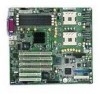
PCI-X, Slots 1 & 2 PO OM15026 AA System Fan 1 BB System Fan 2 CC ID LED DD NIC 1 (10/100) EE NIC 2 (1 gigabit) FF System I/O Connectors GG DIMM Sockets HH Aux Power II Main Power JJ CPU1 Fan Connector KK CPU2 Fan Connector Figure 1. Server Board Connector and Component Locations 2 M-ROMB support - Intel SE7501BR2 | Product Guide - Page 12
DIMM Memory Connect DIMM Memory Connect USB E AB C DF G A. USB 1, 2, 3 B. Keyboard / Mouse C. Serial A D. Video E. Parallel F. NIC2 (Gigabit) G. NIC1 (10/100 Mb) OM14663 Figure 2. Back Panel Connectors Intel® Chipset The Intel® Server Board SE7501BR2 includes the Intel E7501 chipset (MCH - Intel SE7501BR2 | Product Guide - Page 13
controllers • APIC and 8259 interrupt controller • Power management • General purpose I/O • System RTC Super I/O The National Semiconductor† PC87417 Super I/O Plug-and-Play Compatible with ACPI-Compliant Controller/Extender is used on the SE7501BR2 server board. This device provides the system with - Intel SE7501BR2 | Product Guide - Page 14
one processor is installed, it should be in the socket labeled CPU1 and the other socket must be empty. For a complete list of supported processors, see: http://support.intel.com/support/motherboards/server/SE7501BR2 Dual Processor Operation The Intel Xeon processor interface is dual-processor (DP - Intel SE7501BR2 | Product Guide - Page 15
must be identical within the banks. For a list of tested memory, see: http://support.intel.com/support/motherboards/server/SE7501BR2 PCI I/O Subsystem The SE7501BR2 server board provides three PCI bus segments: • Segment C with two PCI-X 64-bit / 100 MHz slots (Slot 1 and 2)3 • Segment B with two - Intel SE7501BR2 | Product Guide - Page 16
(MB/s) • 8-, 16-, 32-, or 64-bit data transfers • Plug-and-Play ready • Parity enabled ✏ NOTE If you install a slower card into one of the PCI-X 64/100 connectors, the bus speed for both connectors will be lowered to the speed of the slowest adapter. 16 Intel Server Board SE7501BR2 Product Guide - Intel SE7501BR2 | Product Guide - Page 17
RAID on Motherboard The SE7501BR2 server board supports M-ROMB or Zero Channel RAID (ZCR) that allows the on-board SCSI controller to be "hidden" from the system and used by the RAID processor on the add-in card. This support is provided via hardware and BIOS support on PCI-X Slot 4. This PCI - Intel SE7501BR2 | Product Guide - Page 18
component terminates the 100Base-TX connector interface. A flash device stores the network ID • Support for Wake on LAN (WOL) • Advanced Networking Service Features (Teaming, Load balancing) 5 NIC1 is the designated Intel Server Management NIC. 18 Intel Server Board SE7501BR2 Product Guide - Intel SE7501BR2 | Product Guide - Page 19
NIC Connector and Status LEDs The Intel® Server Board SE7501BR2 supports two RJ45 connectors, one for the 10/100-Megabit Fast Ethernet controller (NIC1), and the other for the Gigabit Ethernet controller (NIC2). NIC1 drives two LEDs on its RJ45 connector. These LEDs indicate link/activity on the LAN - Intel SE7501BR2 | Product Guide - Page 20
processing is halted. In this state the power supply is still on and the processors still dissipate some power, so the power supply fan and processor fans are still running. ✏ NOTE ACPI requires an operating system that supports this feature. The server board supports sleep states S0, S1, S4, and S5 - Intel SE7501BR2 | Product Guide - Page 21
Management Controller Intel server boards incorporate a baseboard management controller (BMC), which is a dedicated microcontroller for system management activities. The BMC performs the following functions: • Monitors system components and sensors, including processors, memory, fans, power supplies - Intel SE7501BR2 | Product Guide - Page 22
• Power supply failure • Memory error • POST error • Processor fault resilient booting (FRB) failure • Fatal nonmaskable interrupt (NMI) from a source other than the front panel switch • Watchdog timer reset, power down, or power cycle • System restart (reboot) 22 Intel Server Board SE7501BR2 - Intel SE7501BR2 | Product Guide - Page 23
Control or the Client System Setup Utility applications in Intel Server Management. You can configure the EMP by using the Server Configuration Wizard or the System Setup Utility. EMP and Serial Over LAN The Serial B port 10-pin header on the board can be configured in several different ways: as - Intel SE7501BR2 | Product Guide - Page 24
installed. Instructions for creating a service partition are available on the Quick Start Users guide. For more information on Intel Server Management and the individual ISM applications, see the Intel Server Management Installation and User's Guide on the ISM CD. 24 Intel Server Board SE7501BR2 - Intel SE7501BR2 | Product Guide - Page 25
Security The SE7501BR2 BIOS provides a number of security Power On/Reset Set feature to Write Protect in Setup Behavior On-board video goes blank if selected in Setup. Floppy writes are disabled if selected in Setup. Except for the password, no mouse or keyboard input is accepted. Keyboard LEDs - Intel SE7501BR2 | Product Guide - Page 26
the user password to use the keyboard or mouse. • You cannot turn off system power or reset the server from the front panel switches. Secure mode has no effect on functions enabled via the Server Manager Module or power control via the real time clock. 26 Intel Server Board SE7501BR2 Product Guide - Intel SE7501BR2 | Product Guide - Page 27
Password Protection The BIOS uses passwords to prevent unauthorized tampering with the system. Entering the user password permits the modification of the time, date, language, user password, and password on boot setup fields. When a user password is configured, the server can be booted into secure - Intel SE7501BR2 | Product Guide - Page 28
masked, the system power cannot be turned off with the power button after booting the operating system. Termination is also disabled. Termination is a feature that terminates system power when the power switch is held down for more than four seconds. 28 Intel Server Board SE7501BR2 Product Guide - Intel SE7501BR2 | Product Guide - Page 29
it. Otherwise, personal injury or equipment damage can result. Risk of burn: If the server has been running, any installed processor and heat sink on the processor will be hot. To avoid the possibility of a burn, be careful when removing or installing server board components that are located near - Intel SE7501BR2 | Product Guide - Page 30
higher) and operating at the same (or higher) speed as the microprocessor used on this server board. Server board diagram label provided: Place the label inside the chassis in an easy-to-see location, preferably oriented similarly to the server board. 30 Intel Server Board SE7501BR2 Product Guide - Intel SE7501BR2 | Product Guide - Page 31
/SE7501BR2 Processor Minimum of one Intel Xeon processor with 512K cache support. For a complete list of supported processors, see: http://support.intel.com/support/motherboards/server/SE7501BR2 Memory Minimum of two 128 MB ECC, DDR266 compliant registered DIMMs on 184-pin gold DIMMs. Power Supply - Intel SE7501BR2 | Product Guide - Page 32
sized shield from the chassis supplier. Attaching the Gasket to the I/O Shield 1. Remove the backing strip from the gasket. 2. Press the gasket onto the inside face of the I/O shield as shown. OM14074 Figure 3. Attaching the Gasket to the I/O Shield 32 Intel Server Board SE7501BR2 Product Guide - Intel SE7501BR2 | Product Guide - Page 33
the Label to the I/O Shield Installing the I/O Shield The shield fits the rectangular opening in the back of a chassis. The shield has cutouts that match the I/O ports on the server board. Install the shield from inside the chassis before installing the server board. 1. Position one edge so - Intel SE7501BR2 | Product Guide - Page 34
of whether one or two processors will be installed. Standoffs are included with your chassis. Your chassis may be different from the illustration. 1 P P 20 PP PP 4 P P 23 18 5 6 16 19 26 OM14626 Figure 6. Configuring Chassis Standoffs 34 Intel Server Board SE7501BR2 Product Guide - Intel SE7501BR2 | Product Guide - Page 35
Installing the Rubber Bumper 1. Measure and mark the bumper placement location in your chassis firmly into position in the chassis. 1 7 20 P P P P P P 4 8 P 18 7 P 0 23 6 19 26 3" (7.6 cm) OM14835 Figure 7. Installing the Rubber Bumper Server Board Installation and Upgrades 35 - Intel SE7501BR2 | Product Guide - Page 36
came with your chassis, mount the board to the chassis. 1 2 Figure 8. Attaching the Server Board OM14836 ✏ NOTE If a single processor is to be used, insert the screws provided into the four standoffs that border the empty processor socket (CPU2). 36 Intel Server Board SE7501BR2 Product Guide - Intel SE7501BR2 | Product Guide - Page 37
CPU2 Fan E. Processor Power F. System Fans 6, 5, 4, 3 (reading from top to bottom) OM14422 G. Front Panel H. Chassis Intrusion I. ATA 100 IDE J. Floppy Disk Drive Connector K. System Fans 1, 2 (reading from top to bottom) Figure 9. Making Connections to the Server Board Server Board Installation - Intel SE7501BR2 | Product Guide - Page 38
that connect to devices in the lower device bays should be routed around the fan housing and ducts as shown below. Floppy Drive Cable Route the floppy drive cable as shown. Route cables here OM14641 Figure 10. Routing the SCSI and Floppy Drive Cable 38 Intel Server Board SE7501BR2 Product Guide - Intel SE7501BR2 | Product Guide - Page 39
your server can handle a newer, faster processor (thermal and power considerations). For exact information about processor interchangeability, contact your customer service representative or visit the Intel Customer Support website: http://support.intel.com/support/motherboards/server/SE7501BR2 ESD - Intel SE7501BR2 | Product Guide - Page 40
a Reference Chassis Use these instructions if you are installing a processor and the Processor Wind Tunnel (PWT) in the SC5200 chassis or in a reference chassis. If you are installing the Server Board SE7501BR2 in the Intel® Server Chassis SC5200 Hot Swap Redundant Power, disregard this section and - Intel SE7501BR2 | Product Guide - Page 41
mechanism over the top of the processor with the screws provided, as shown in Figure 12. OM15037 Figure 12. Attaching Retention Mechanism 7. Apply thermal grease to the top of the processor as shown in Figure 13. OM15040 Figure 13. Applying Thermal Grease Server Board Installation and Upgrades 41 - Intel SE7501BR2 | Product Guide - Page 42
8. Align the heat sink over the processor and set it into place. 9. Position the retention clips over the plastic tabs at the tab engages in the heat sink base. A C B C E 1 3 D 2 4 OM15039A Figure 14. Attaching the Heat Sink and Retention Clip 42 Intel Server Board SE7501BR2 Product Guide - Intel SE7501BR2 | Product Guide - Page 43
side of the fan assembly component of the PWT (Figure 15, B). To ensure that the airflow direction is correct, insert the fan so that the label shows through the assembled unit (Figure 15, A). B A B C OM15041 Figure 15. Attaching the Wind Tunnel Fan Server Board Installation and Upgrades 43 - Intel SE7501BR2 | Product Guide - Page 44
fan assembly (Figure 16, 2) and insert them into the corresponding slots (Figure 16, 3). Rotate the fan assembly downward to engage the clips at the bottom (Figure 16, 4). 2 2 1 3 4 OM15044 Figure 16. Attaching the Heat Sink Fan to the Top of the PWT 44 Intel Server Board SE7501BR2 Product Guide - Intel SE7501BR2 | Product Guide - Page 45
Figure 17, 2). 15. Attach CPU Fan 1 cable to the server board at location J7F21 and/or attach CPU Fan 2 cable at location J5F1. fan is toward the front of the chassis and the airflow is toward the I/O shield. If two processors are installed, the fans should be side by side. Server Board Installation - Intel SE7501BR2 | Product Guide - Page 46
18, B) indicate that this processor assembly is only required when configuring the server with two processors. The direction of the airflow is indicated by the arrow at (Figure 18, C). A B C Figure 18. Processor and Wind Tunnel Installed OM15038 46 Intel Server Board SE7501BR2 Product Guide - Intel SE7501BR2 | Product Guide - Page 47
the following: 1. Place the bracket (letter A in the following diagram) on the server board. 2. Insert and tighten two screws (letter B in the diagram) to secure the bracket to the board. B A OM14144 Figure 19. Installing the Processor Retention Brackets Server Board Installation and Upgrades 47 - Intel SE7501BR2 | Product Guide - Page 48
the Locking Bar 4. Aligning the pins of the processor with the socket, insert the processor into the socket. ✏ NOTE Make sure the alignment triangle mark and the alignment triangle cutout align correctly. OM14133 Figure 21. Installing Processors 48 Intel Server Board SE7501BR2 Product Guide - Intel SE7501BR2 | Product Guide - Page 49
5. Lower the locking bar completely. Figure 22. Lower Locking Bar OM14135 6. Apply thermal grease to the top of the processor as shown. OM14366 Figure 23. Applying Thermal Grease Server Board Installation and Upgrades 49 - Intel SE7501BR2 | Product Guide - Page 50
7. Position the heat sink above the processor 8. Aligning the raised metal surfaces, place the heat sink on top of the processor. OM14134 Figure 24. Installing the Heat Sink 50 Intel Server Board SE7501BR2 Product Guide - Intel SE7501BR2 | Product Guide - Page 51
clip down (3). 2 1 A 3 OM14140 Figure 25. Installing the Heat Sink Clip Replacing a Processor 1. Observe the safety and ESD precautions at the beginning of this chapter and the additional cautions given here. 2. Unplug the processor fan cable from the server board. 3. For a chassis in which a PWT - Intel SE7501BR2 | Product Guide - Page 52
mix various sizes of DIMMs between banks, DIMMs must be identical within the banks. For a list of tested memory, see: http://support.intel.com/support/motherboards/server/SE7501BR2 DIMM 1A DIMM 1B DIMM 2A DIMM 2B Figure 26. Installing Memory OM14665 52 Intel Server Board SE7501BR2 Product Guide - Intel SE7501BR2 | Product Guide - Page 53
to complete rack or pedestal installation. 3. Connect the keyboard, mouse and monitor cables to the back panel. 4. Connect the power cable to the back panel and to an AC outlet. A C E D B G F I H OM14669 Figure 27. Making Back Panel Connections Server Board Installation and Upgrades 53 - Intel SE7501BR2 | Product Guide - Page 54
on the server board powers the real time clock (RTC) for at least three years in the absence of power. When the battery starts to weaken, it loses voltage, and the server settings stored in CMOS RAM in the RTC (for example, the date and time) may be wrong. If you are using Intel Server Management - Intel SE7501BR2 | Product Guide - Page 55
the new lithium battery from its package, and, being careful to observe the correct polarity, insert it in the battery socket. 7. Close the chassis. 8. Run Setup to restore the configuration settings to the RTC. Server Board Installation and Upgrades 55 - Intel SE7501BR2 | Product Guide - Page 56
56 Intel Server Board SE7501BR2 Product Guide - Intel SE7501BR2 | Product Guide - Page 57
BIOS Setup utility. Power-On Self-Test (POST) Each time you turn on the system, the BIOS begins executing the Power-On Self-Test (POST), which is stored in flash memory. POST discovers, configures, and tests the processors, memory, keyboard, and most installed peripheral devices. During the memory - Intel SE7501BR2 | Product Guide - Page 58
configuration jumper block on the baseboard. Starting Setup You can enter and start Setup under several conditions: • When you turn on the server, after POST completes the memory test • When you have moved the CMOS jumper on the server board to the "Clear CMOS" position (enabled). For instructions - Intel SE7501BR2 | Product Guide - Page 59
106-key Japanese keyboards, the plus key has a different scan code than the plus key on the other keyboard, but it has window is displayed and the user is asked whether changes can be discarded. Setup Defaults - Pressing F9 causes the following to appear: Setup Confirmation Load default configuration - Intel SE7501BR2 | Product Guide - Page 60
Security Server Boot Allocates resources for hardware components Configures advanced features available through the chipset Sets and clears Information on Selects boot passwords and Vendor, options and security features Processor, power supply Memory, controls Peripherals, and BIOS - Intel SE7501BR2 | Product Guide - Page 61
> Secondary IDE Master Secondary IDE Slave Processor Settings Language English (US) Spanish Italian French German Type None Auto Auto instructs the system to automatically detect the drive type. None instructs the system to ignore . POST and the BIOS Setup Utility 61 - Intel SE7501BR2 | Product Guide - Page 62
if you want to clear the server configuration data during the next boot. The system automatically resets this field to No during the next boot. Selects the state of the Numlock key at system power-on. When disabled, the sleep button will be disabled. 62 Intel Server Board SE7501BR2 Product Guide - Intel SE7501BR2 | Product Guide - Page 63
resources are hidden from the system. On-board SCSI ROM Enabled Disabled When enabled, the SCSI device expansion ROM is initialized. On-board Video Enabled Disabled When disabled, the embedded video is disabled and the device resources are hidden from the system. POST and the BIOS Setup - Intel SE7501BR2 | Product Guide - Page 64
Peripheral Configuration Submenu Support Disabled Keyboard only Auto Keyboard and Mouse If disabled, legacy USB support is turned off at the end of BIOS POST. Front Panel USB Enabled Disabled If disabled, the front panel USB ports are inactive. 64 Intel Server Board SE7501BR2 Product Guide - Intel SE7501BR2 | Product Guide - Page 65
Extended Memory Test 1 MB 1 KB Every Location Disabled Selects the size of step to use during the extended RAM tests. When disabled is selected, extended memory tests are not run. The Every Location selection will increase the boot time. Memory Bank #1 (DIMM 1A, 1B) Installed Not Installed - Intel SE7501BR2 | Product Guide - Page 66
remain in secure mode until password is entered. This option is only available if a User Password is configured. When Write Protect is enabled, the boot sector of the hard drive is protected. This prevents viruses from corrupting the drive. continued 66 Intel Server Board SE7501BR2 Product Guide - Intel SE7501BR2 | Product Guide - Page 67
submenu. Enters submenu. When enabled, PCI bus parity errors (PERR) cause a system NMI. When enabled, PCI bus system errors (SERR) cause a system NMI. This option determines when the Boot Strap Processor should be disabled if an FRB-2 error occurs. continued POST and the BIOS Setup Utility 67 - Intel SE7501BR2 | Product Guide - Page 68
Service Boot Always Reset PXE OS Boot Timeout Disable 5 minutes 10 minutes 15 minutes 20 minutes When enabled, the system will wait for user intervention if a critical POST error configures BIOS installed Information only Information only continued 68 Intel Server Board SE7501BR2 Product Guide - Intel SE7501BR2 | Product Guide - Page 69
the COM port for console redirection, the flow control must be set to CTS/RTS or to CTS/RTS +CD, depending on whether a modem is used. Terminal Type PC-ANSI VT100+ VT-UTF8 This option selects the character with English. PC-ANSI is the standard PC-type terminal. POST and the BIOS Setup Utility 69 - Intel SE7501BR2 | Product Guide - Page 70
Disabled This option controls the amount of time permitted to load the operating system from a device that is compliant with the PXE specification. This option is not available if the Boot Monitoring option on the Server Menu is not set to Disabled. 70 Intel Server Board SE7501BR2 Product Guide - Intel SE7501BR2 | Product Guide - Page 71
cards Use the minus (-) key to move the device down in the list. Each drive with a PnP header "Other bootable cards" indicates boot devices that are not reported to the system BIOS through the BIOS boot specification mechanism. These devices may or may not be bootable. POST and the BIOS Setup - Intel SE7501BR2 | Product Guide - Page 72
setup fields were modified. Load default values for all SETUP items. Load values from previously saved custom defaults. This option is not available if no custom defaults are detected. Stores custom defaults in NVRAM. Read previous values from NVRAM. 72 Intel Server Board SE7501BR2 Product Guide - Intel SE7501BR2 | Product Guide - Page 73
or from the Intel Customer Support website: http://support.intel.com/support/motherboards/server/SE7501BR2 ✏ NOTE Review the instructions distributed with the upgrade utility before performing a BIOS upgrade. This upgrade utility allows you to upgrade the BIOS in flash memory. The following steps - Intel SE7501BR2 | Product Guide - Page 74
enter Setup, check your settings, save your settings, and exit Setup. It is unlikely that anything will interrupt the BIOS upgrade; however, if an interruption occurs, the BIOS could be damaged. See "Recovering the BIOS" on page 112 for instructions. 74 Intel Server Board SE7501BR2 Product Guide - Intel SE7501BR2 | Product Guide - Page 75
language that the BIOS uses for messages and for the Setup program. Use a bootable diskette containing the Intel flash utility and language files. 1. Boot the computer with the bootable diskette in drive A. The BIOS upgrade utility screen appears. 2. Select Update Flash Memory From a File. 3. Select - Intel SE7501BR2 | Product Guide - Page 76
- Intel SE7501BR2 | Product Guide - Page 77
FRU/SDR 3. Unplug system for 30 seconds 4. Update BIOS 5. Clear CMOS Table 31. Configuration Utilities Utility Description and brief procedure Server Configuration Wizard Use to configure the server, including creating and modifying the service partition, setting the system date and time, load - Intel SE7501BR2 | Product Guide - Page 78
Resource CD-ROM shipped with the server and it runs automatically when you boot your server to this CD-ROM. The Server Configuration Wizard includes a help system that can be accessed by clicking the Help button. Run the Configuration to: • Create or update a Service Partition and install service - Intel SE7501BR2 | Product Guide - Page 79
change your processors. Assign an identification number or serial number to the server. If a service partition does not already exist, create one. If a service partition has been created earlier, update it. Create diskettes by operating system, utility, or device driver. Save the configuration data - Intel SE7501BR2 | Product Guide - Page 80
of files. Running the DPC Console For more information about setting up and running the DPC Console, see the ISM Installation User's Guide. This document is in the ISM\DOCS\[language] directory on the ISM CD accompanying the SE7501BR2 server board. 80 Intel Server Board SE7501BR2 Product Guide - Intel SE7501BR2 | Product Guide - Page 81
follows: 1. Boot the System Resource CD-ROM to the Server Configuration Wizard. 2. Choose Create Diskettes > Create Diskettes by Device/Function > System Setup Utility. 3. Follow the instructions displayed. Alternatively, if you have a workstation with the Microsoft Windows operating system, you can - Intel SE7501BR2 | Product Guide - Page 82
to avoid possible conflicts. The tasks achieve complete control by keeping the task as the center of operation until you close the task window. The SSU has a build-in help system, which you access by clicking a Help button or choosing the Help menu. 82 Intel Server Board SE7501BR2 Product Guide - Intel SE7501BR2 | Product Guide - Page 83
password and an administrator password for the server. You must set an administrator password before you can set a user password. On other systems, the passwords are independent. You can set the same passwords and security options by using BIOS Setup. Setting the Administrator Password The Admin - Intel SE7501BR2 | Product Guide - Page 84
the power and reset buttons from functioning when the server is in secure mode. Disable allows the power and reset buttons to function normally when the server is in secure mode. 3. Click Save to save the settings and return to the Security window. 84 Intel Server Board SE7501BR2 Product Guide - Intel SE7501BR2 | Product Guide - Page 85
loads the current list of events from non-volatile memory. The FRU Manager window has a navigation pane on the left that displays, in a tree format, the inventory of components in the server. The tree has three categories: Chassis, Board, and Product. Clicking on a category expands or collapses - Intel SE7501BR2 | Product Guide - Page 86
SSU. You can download the updates from the Intel support website: http://support.intel.com/support/motherboards/server Updating the BIOS To update the BIOS: 1. Download the update from the Intel support website. 2. From the SSU Main window, choose System Update. (System Update is available only in - Intel SE7501BR2 | Product Guide - Page 87
for the update. 4. Click the Update button to perform the update. Verifying the Firmware To compare the system firmware in nonvolatile memory with a firmware file: 1. Download the update from the Intel support website. 2. From the SSU Main window, choose System Update. (System Update is available - Intel SE7501BR2 | Product Guide - Page 88
regardless of the server's state or health • Restricted: power control functions, such as power down, front Setup Utility to configure remote LAN access: 1. From the SSU Main window, choose Platform Event Manager (PEM). 2. In the PEM window, click Configure Intel Server Board SE7501BR2 Product Guide - Intel SE7501BR2 | Product Guide - Page 89
can use either the Server Configuration Wizard or the System Setup Utility. To use the Server Configuration Wizard to configure remote modem or serial access: 1. Use the Resource CD to boot the server to the Server Configuration Wizard. 2. Select Server Configuration Wizard and Continue. 3. Select - Intel SE7501BR2 | Product Guide - Page 90
Connect: the Serial B port on the server is connected by a serial cable to the remote system. • Modem Connect: the Serial B port on the server is connected to a modem. 9. Click Save to save the changes. 10. Click Close to return to the PEM window. 90 Intel Server Board SE7501BR2 Product Guide - Intel SE7501BR2 | Product Guide - Page 91
Server Configuration Wizard or the System Setup Utility. To use the Server Configuration Wizard to configure the server to send alerts as telephone pages: 1. Use the Resource CD to boot the server to the Server Configuration Wizard. 2. Select Server Configuration when the server is powered down or - Intel SE7501BR2 | Product Guide - Page 92
the PEP Configuration window. 15. To send a test page to verify that you have correctly configured PEP, from the Options menu, choose Send Alert. 16. Click Save to save the configuration. 17. Click Close to return to the Platform Event Manager window. 92 Intel Server Board SE7501BR2 Product Guide - Intel SE7501BR2 | Product Guide - Page 93
alerts, see the documentation for Intel Server Management software. To use the Server Configuration Wizard to configure the server to send alerts over the LAN: 1. Use the Resource CD to boot the server to the Server Configuration Wizard. 2. Select Server Configuration Wizard and Continue. 3. Select - Intel SE7501BR2 | Product Guide - Page 94
events from the disabled list to the enabled list. 10. Click Save to save the changes. 11. Click Close to return to the BMC LAN Configuration window. 12. Click Save to save the changes. 13. Click Close to return to the PEM window. 94 Intel Server Board SE7501BR2 Product Guide - Intel SE7501BR2 | Product Guide - Page 95
-band update instructions, refer to the Intel® Server Management Installation and User's Guide. The Firmware Update Utility is a DOS-based program used to update the BMCs firmware code. You need to run the utility only if new firmware code is necessary. How to Run the Firmware Update Utility Review - Intel SE7501BR2 | Product Guide - Page 96
the system's field replaceable units A .cfg file describing the system configuration An .sdr file describing the sensors in the system The command line format to do this is: FRU/SDR [-?] [-h] [-d {fru, sdr}] [-cfg filename.cfg] [-fru filename.fru] 96 Intel Server Board SE7501BR2 Product Guide - Intel SE7501BR2 | Product Guide - Page 97
: -cfg filename.cfg. Invalid parameters cause an error message and exit the program. You can use either memory and printed on the screen. Each area represents one sensor for each instrumented device in the server for Product Level FRU Information With a configuration file, the utility might prompt you - Intel SE7501BR2 | Product Guide - Page 98
. Creating Diskettes You can use the Resource CD to create diskettes for device drivers or for server management utilities. You can create diskettes for the NIC drivers, video drivers or SCSI drivers. You can also create diskettes to use for running the System Setup Utility and the FRU/SDR Load - Intel SE7501BR2 | Product Guide - Page 99
Installation and User's Guide for Intel Server Management. This document is included on the ISM CD shipped with your server board. To install the service partition use the Server Configuration Wizard 1. Use the Resource CD to boot the server to the Server Configuration Wizard. 2. Select the Server - Intel SE7501BR2 | Product Guide - Page 100
configuration from the Server Configuration Wizard: 1. Follow the configuration prompts until you see "Save Server Configuration." 2. Select the "Save Server Configuration" checkbox and click Continue. 3. Specify a filename and location as prompted. 100 Intel Server Board SE7501BR2 Product Guide - Intel SE7501BR2 | Product Guide - Page 101
the Resource CD into the Server Configuration Wizard. 2. Select the Server Configuration Wizard > Load from Diskette. Click continue. ✏✏ NOTE You can load only a configuration that had been previously saved with the Server Configuration Wizard. The utility reads the platform type, BIOS revision - Intel SE7501BR2 | Product Guide - Page 102
/DOCS folder on the Intel Server Management CD-ROM. SMaRT Tool and ISM Console may only be installed on a system running a Microsoft Windows operating system. ✏✏ NOTE Prior to installation, uninstall any previous version of Intel Server Management. 102 Intel Server Board SE7501BR2 Product Guide - Intel SE7501BR2 | Product Guide - Page 103
SMaRT Tool Setup program. 7. Follow the on-screen installation instructions. Review the Intel Software License Agreement and click Accept. When installation is complete, launch SMaRT Tool. 8. In SMaRT Tool's Welcome page, click on Systems. 9. Select Select System > Servers > Xeon > SE7501BR2 SR5200 - Intel SE7501BR2 | Product Guide - Page 104
104 Intel Server Board SE7501BR2 Product Guide - Intel SE7501BR2 | Product Guide - Page 105
the wall outlet? ! Are the power supplies plugged in? Check the AC cable on the back of the chassis and at the AC source. ! Are all cables correctly connected and secured? ! Are the processors fully seated in their sockets on the server board? ! Are all add-in PCI boards fully seated in their slots - Intel SE7501BR2 | Product Guide - Page 106
corrupted by voltage spikes on your power line. If you are experiencing any of the above symptoms that might indicate voltage spikes on the power line, you may want to install a surge suppressor between the power outlet and the system power cord. 106 Intel Server Board SE7501BR2 Product Guide - Intel SE7501BR2 | Product Guide - Page 107
on the system. If the power LED does not light, see "Power Light Does Not Light" on page 110. Monitoring POST See Chapter 3. Verifying Proper Operation of Key System Lights As POST determines the system configuration, it tests for the presence of each mass storage device installed in the system. As - Intel SE7501BR2 | Product Guide - Page 108
in and turned on? ! Are the brightness and contrast controls on the video monitor properly adjusted? ! Are the video monitor switch settings correct? ! Is the video monitor signal cable properly installed? ! Is the onboard video controller enabled? 108 Intel Server Board SE7501BR2 Product Guide - Intel SE7501BR2 | Product Guide - Page 109
manufacturer's documentation. ! Are the video monitor's signal and power cables properly installed? If the problem persists, the video monitor may be faulty or it may be the incorrect type. Contact your service representative or authorized dealer for help. System Cooling Fans Do Not Rotate Properly - Intel SE7501BR2 | Product Guide - Page 110
LED is not connected to the SE7501BR2 server board front panel. CD-ROM Drive Activity Light Does Not Light Check the following: ! Are the CD-ROM drive's power and signal cables properly installed? ! Are all relevant switches and jumpers on the drive set correctly? ! Is the drive properly configured - Intel SE7501BR2 | Product Guide - Page 111
activity LED is not connected to the SE7501BR2 server board front panel. The controller stopped working when an add-in adapter was installed. ! Make sure the cable is connected to the port from the onboard network controller. ! Make sure your PCI BIOS is current. Try the "PCI Installation Tips - Intel SE7501BR2 | Product Guide - Page 112
series of short beeps. 1. Create a bootable diskette that contains the BIOS update file and the iFLASH.EXE utility. This is available from: http://support.intel.com/support/motherboards/server/SE7501BR2 2. Turn off the system power and disconnect the AC power. 3. Open the server chassis. 4. Move the - Intel SE7501BR2 | Product Guide - Page 113
a continuous series of beeps. When the flash update completes: 1. Turn off the system power and remove the AC power. 2. Remove the recovery diskette. 3. Restore the BIOS recovery jumper to its original position, covering pins 9 and 10. 4. Close the server chassis. 5. Replace the AC power and turn on - Intel SE7501BR2 | Product Guide - Page 114
diagram. Figure 30. Password Recovery Jumper 4. Reconnect the AC power, power up the system. 5. Power down the system and disconnect the AC power. 6. Return the Password Clear jumper to its original position, covering pins 5 and 6. 7. Close the server chassis. 114 Intel Server Board SE7501BR2 - Intel SE7501BR2 | Product Guide - Page 115
not able to access the BIOS setup screens, the CMOS Clear jumper will need to be used to reset the configuration RAM. The CMOS Clear jumper is located on jumper block J1H1 on the SE7501BR2 board. 1. Power down the system and disconnect the AC power. 2. Open the server. 3. Move the CMOS Clear jumper - Intel SE7501BR2 | Product Guide - Page 116
116 Intel Server Board SE7501BR2 Product Guide - Intel SE7501BR2 | Product Guide - Page 117
Wide Web http://support.intel.com/support/motherboards/server/SE7501BR2 Telephone All calls are billed US $25.00 per incident, levied in local currency at the applicable credit card exchange rate plus applicable taxes. (Intel reserves the right to change the pricing for telephone support at any - Intel SE7501BR2 | Product Guide - Page 118
118 Intel Server Board SE7501BR2 Product Guide - Intel SE7501BR2 | Product Guide - Page 119
Jumper Location J106 OM14670 Table 33. Configuration Jumper (J1H1) Jumper Name Pins What happens at for normal operation. BIOS normal operation 9-10 These pins are for normal operation. BIOS Recovery 10-11 If these pins are jumpered, the system will attempt BIOS recovery. These pins - Intel SE7501BR2 | Product Guide - Page 120
& 13 Pressing the power switch removes all by standby power from the board 7 & 9 LED show hard disk drive activity 1 & 5 LED shows power on 22 & 24 LED shows network interface controller activity 12 & 14 LED shows network interface controller activity 120 Intel Server Board SE7501BR2 Product Guide - Intel SE7501BR2 | Product Guide - Page 121
) Product EMC Compliance The SE7501BR2 has been has been tested and verified to comply with the following electromagnetic compatibility (EMC) regulations when installed a compatible Intel® host system. For information on compatible host system(s) refer to Intel's Server Builder website or contact - Intel SE7501BR2 | Product Guide - Page 122
35. Product Certification Markings UL Recognition Mark CE Mark Russian GOST Mark Australian C-Tick Mark BSMI DOC Marking BSMI EMC Warning RRL MIC Mark 122 Intel Server Board SE7501BR2 Product Guide - Intel SE7501BR2 | Product Guide - Page 123
this product, contact: Intel Corporation 5200 N.E. Elam installation. This equipment generates, uses, and can radiate radio frequency energy and, if not installed and used in accordance with the instructions shielded and grounded. Operation with cables, connected to peripherals, that are not shielded - Intel SE7501BR2 | Product Guide - Page 124
Recipient: Intel 4. Date of Manufacturer: Marked on Product 5. Manufacturer / Nation : Intel Australia / New Zealand This product has been tested and complies with AS/NZS 3548. The product has been marked with the C-Tick mark to illustrate compliance. 124 Intel Server Board SE7501BR2 Product Guide - Intel SE7501BR2 | Product Guide - Page 125
pins, 39 handle boards carefully, 30 power button does not turn off system AC power, 29 selecting correct processor, 39 chassis cover, install, 53 Chassis intrusion, 28 chipset, 9 Client System Setup Utility, 77 CMOS, 58, 77 corrupted, 58 jumper, 58 cold boot, 105 Configuration how to restore - Intel SE7501BR2 | Product Guide - Page 126
, 80 controller diskette, 64 Ethernet, 10 floppy disk, 13 keyboard, 13 memory, 12 mouse, 13 network, 9, 18 SCSI, 16 video, 9, 17, 67 CPU fan cable install, 45 removing, 51 CRT displays, 17 CSSU, 77 D device driver, how to create diskettes, 98 diagnostics, preparing system for testing, 107 DIMM - Intel SE7501BR2 | Product Guide - Page 127
, 75 I I/O PCI expansion slots, 9 ports provided, 10 I/O shield, 31, 32, 45 attaching gasket, 32 attaching label, 33 installing, 33 I/O subsystem core, 12 ICH3 features, 13 role, 13 ICH3 I/O controller, 9 ICH3-S, 12 IDE, configuring, 60 IDE interface, 13 iFLASH, 73, 113 Intel® Server Management, 21 - Intel SE7501BR2 | Product Guide - Page 128
system for diagnostic testing, 107 random error in data files, 106 screen characters incorrect, 109 system cooling fans do not rotate, 109 system lights, 107 processor adding second processor, 39 apply thermal grease, 41, 49 heat sink, 42, 50 128 Intel Server Board SE7501BR2 Product Guide - Intel SE7501BR2 | Product Guide - Page 129
, 64, 69 serial port connector, 13 server board component locations, figure, 11 how to install, 36 server board jumpers, location, 119 Server Configuration Wizard, 77, 78 Server management, configuring, 67 Service Partition, 24, 99 how to create, 99 Setup, 58 Advanced Menu, 62 Boot Menu, 71 - Intel SE7501BR2 | Product Guide - Page 130
, configuring, 65 Wake on Ring, 10, 21 configuring, 65 Wake on RTC alarm, 21 configuring, 65 Warning components may be hot, 29 dispose of lithium battery safely, 54 ESD can damage product, 30 hazardous electrical conditions, 29 WOL, see Wake on LAN18 130 Intel Server Board SE7501BR2 Product Guide
-
 1
1 -
 2
2 -
 3
3 -
 4
4 -
 5
5 -
 6
6 -
 7
7 -
8
-
9
-
10
-
11
-
12
-
13
-
14
-
15
-
16
-
17
-
18
-
19
-
20
-
21
-
22
-
23
-
24
-
25
-
26
-
27
-
28
-
29
-
30
-
31
-
32
-
33
-
34
-
35
-
36
-
37
-
38
-
39
-
40
-
41
-
42
-
43
-
44
-
45
-
46
-
47
-
48
-
49
-
50
-
51
-
52
-
53
-
54
-
55
-
56
-
57
-
58
-
59
-
60
-
61
-
62
-
63
-
64
-
65
-
66
-
67
-
68
-
69
-
70
-
71
-
72
-
73
-
74
-
75
-
76
-
77
-
78
-
79
-
80
-
81
-
82
-
83
-
84
-
85
-
86
-
87
-
88
-
89
-
90
-
91
-
92
-
93
-
94
-
95
-
96
-
97
-
98
-
99
-
100
-
101
-
102
-
103
-
104
-
105
-
106
-
107
-
108
-
109
-
110
-
111
-
112
-
113
-
114
-
115
-
116
-
117
-
118
-
119
-
120
-
121
-
122
-
123
-
124
-
125
-
126
-
127
-
128
-
129
-
130
 |
 |

Intel
®
Server Board SE7501BR2
Product Guide
A Guide for Technically Qualified Assemblers of Intel
®
Identified
Subassemblies/Products
Order Number:
A97020-002