Invacare TDXSC2-CG Owners Manual 2 - Page 92
Place the wheelchair in a well ventilated area where work can be performed without risking damage
 |
View all Invacare TDXSC2-CG manuals
Add to My Manuals
Save this manual to your list of manuals |
Page 92 highlights
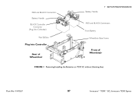
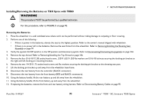
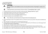
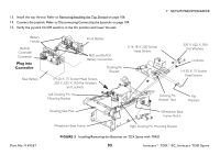
7 SETUP/MAINTENANCE Installing the Batteries ƽ CAUTION Place the wheelchair in a well ventilated area where work can be performed without risking damage to carpeting or floor covering. If replacing the batteries install the battery wiring harness. Refer to Connecting Battery Cables on page 96. 1. If replacing the batteries, install the front and rear battery wiring harness. Refer to Replacing the Batteries on page 95. 2. Using the battery handle and strap, position the front battery into the battery box. 3. Using the battery handle, position the rear battery into the battery box. 4. Connect the rear battery to the front battery (RED and BLACK connectors). 5. Connect the rear battery to the controller (BLACK connector). Ensure rubber pad is positioned between the docking pin bracket and the elevating seat post. 6. Position the docking pin bracket onto the wheelchair base frame so that the four tabs set into the notches in both sides of the wheelchair base frame. 7. Apply loctite® 242 to the threads of the four 5/16-18 X 2.00 socket head screws. 8. Loosely install the four 5/16-18 X 2.00 socket head screws, .330 X .625 X .050 flat washers and 5/16-18 locknuts, secure the docking pin bracket to the right and left docking pin mounting brackets. 9. Apply loctite 242 to the threads of the two 1/4-20 X .75 socket head screws. 10. Loosely install the two 1/4-20 X .75 socket head screws and flat washers, secure the docking pin bracket to the elevating seat post. 11. Securely tighten the four 5/16-18 X 2.00 socket head screws, .330 X .625 X .050 flat washers and 5/16-18 locknuts. Torque to 13ft-lbs ± 20%. 12. Securely tighten the two 1/4-20 X .75 socket head screws and flat washers. Torque to 75i-/lbs ± 20%. Invacare® TDX® SC, Invacare TDX Spree 92 Part No 1149267
-
 1
1 -
2
-
3
-
4
-
5
-
6
-
7
-
8
-
9
-
10
-
11
-
12
-
13
-
14
-
15
-
16
-
17
-
18
-
19
-
20
-
21
-
22
-
23
-
24
-
25
-
26
-
27
-
28
-
29
-
30
-
31
-
32
-
33
-
34
-
35
-
36
-
37
-
38
-
39
-
40
-
41
-
42
-
43
-
44
-
45
-
46
-
47
-
48
-
49
-
50
-
51
-
52
-
53
-
54
-
55
-
56
-
57
-
58
-
59
-
60
-
61
-
62
-
63
-
64
-
65
-
66
-
67
-
68
-
69
-
70
-
71
-
72
-
73
-
74
-
75
-
76
-
77
-
78
-
79
-
80
-
81
-
82
-
83
-
84
-
85
-
86
-
 87
87 -
 88
88 -
 89
89 -
 90
90 -
 91
91 -
 92
92 -
 93
93 -
 94
94 -
 95
95 -
 96
96 -
 97
97 -
98
-
99
-
100
-
101
-
102
-
103
-
104
-
105
-
106
-
107
-
108
-
109
-
110
-
111
-
112
-
113
-
114
-
115
-
116
 |
 |