JVC DZ-VCA3U DZ-VCA3U 24-page Instruction Manual - Page 11
NTSC OUTPUT] NTSC output
 |
View all JVC DZ-VCA3U manuals
Add to My Manuals
Save this manual to your list of manuals |
Page 11 highlights
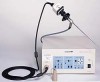
Camera control unit (rear panel) 1 ~AC IN 2 NTSC OUT GENLOCK IN/OUT SXGA OUT HD OUT DV Y/C (S) VBS GBR Y (1) PB GBR (2) PR 3 45 67 1 [AC INPUT] power input connector To input AC120V. 2 Equal-potential connector 3 Cover for extension slot Remove the cover to install an optional device in this slot. 4 [NTSC OUTPUT] NTSC output section Output of DV signals, Y/C(S) signals, VBS (composite video signals). The power supply for IEEE1394 interface is not available from DV connector. Camera head 5 [GENLOCK IN/OUT] sync signal input/output Input/output of composite sync signal for external sync. (menu-based switching). 6 [SXGA OUT] SXGA output section Output of progressive scan GBR signal. SXGA output signal cannot be displayed on the DTV1900CGU.Use the monitor that is compliant with the following scanning frequency. Horizontal: 67.4325kHz, vertical: 59.94Hz 7 [HD OUT] video signal output section Output of HD (Y, PB, PR) video signals (interlace scan). When HD video signals are connected to Hi-vision monitor, the screen will have a width/length ratio of 16:9, and the picture will extend sideways. 1 Lens mount ring Standard C mount is used. Flange back will be 17.526mm in air. 2 Camera cable connector (plug) Connect to camera control unit. 2 11
-
 1
1 -
2
-
3
-
4
-
5
-
 6
6 -
 7
7 -
 8
8 -
 9
9 -
 10
10 -
 11
11 -
 12
12 -
 13
13 -
 14
14 -
 15
15 -
 16
16 -
17
-
18
-
19
-
20
-
21
-
22
-
23
-
24
 |
 |
