Jensen UCD200 Owners Manual - Page 6
Installing The Removable Faceplate
 |
UPC - 043258301659
View all Jensen UCD200 manuals
Add to My Manuals
Save this manual to your list of manuals |
Page 6 highlights
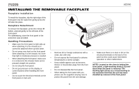
UCD200 INSTALLING THE REMOVABLE FACEPLATE Faceplate Installation To install the faceplate, slip the right edge of the front panel into the radio then gently press the left side into place. Faceplate Detachment To remove the faceplate, press the release button, and pull gently on the left side of the front panel. For safekeeping, store the front panel in the protective case provided. Handling Precautions • Make sure the front panel is right-side-up when attaching it to the chassis as it cannot be attached when up-side down. • Do not press very hard on the front panel when attaching it to the chassis. No more than light to moderate pressure is needed. • When attaching the front panel, make sure it is centered in the chassis frame and is pressed straight into position. • Do not drop the front panel. • Do not put pressure on the display or control buttons when handling the front panel. • Do not touch the electrical terminals on the front panel or main unit. RELEASE PWR EQ SEL / AUDIO EJECT UCD200 1 AMS 2 SCN A M / F M / CD 4 RECE SHF IVE R 5 CD- 3 RPT 6 CD+ LOC MODE DISP TUNE TRACK BAND LOUD/ENTER MO MUT • Remove dirt or foreign substances with a clean, dry cloth only. • Do not expose the front panel to extreme temperatures or direct sunlight. • Keep volatile agents such as benzene, thinner or insecticides away from the front panel. • Do not disassemble the front panel. • When taking the front panel with you, please use the supplied carrying case to protect the panel from dirt and damage. • Make sure there is no dust or dirt on the electrical terminals on the back of the panel as this could cause intermittent operation or other malfunctions. NOTE: Located on the chassis behind the front panel, a light-emitting diode (LED) will flash when the panel is removed. The flashing light serves as a visual warning to the would-be thief that the unit has been disabled by removal of the front panel. 6
-
 1
1 -
 2
2 -
 3
3 -
 4
4 -
 5
5 -
 6
6 -
 7
7 -
 8
8 -
 9
9 -
 10
10 -
 11
11 -
 12
12 -
13
-
14
-
15
-
16
-
17
-
18
-
19
-
20
-
21
-
22
-
23
-
24
-
25
-
26
-
27
-
28
-
29
-
30
-
31
-
32
-
33
-
34
-
35
-
36
-
37
-
38
-
39
-
40
-
41
-
42
-
43
-
44
-
45
-
46
-
47
 |
 |
