Kenmore 4689 Installation Instructions
Kenmore 4689 - 30 in. Slide-In Electric Range Manual
 |
View all Kenmore 4689 manuals
Add to My Manuals
Save this manual to your list of manuals |
Kenmore 4689 manual content summary:
- Kenmore 4689 | Installation Instructions - Page 1
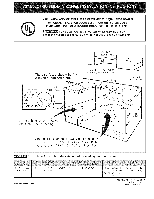
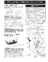
BY A QUALIFIED INSTALLER. IMPORTANT: SAVE FOR LOCAL ELECTRICAL INSPECTOR'S USE. READ AND SAVE THESE INSTRUCTIONS FOR FUTURE REFERENCE - 43.2 cm) From Right Cabinet and 2" to 4" (5.1-10.2 cm) From Floor Do not install the unit in the cabinet before reading next two pages. 35 7/8" (91.1cm) 36 5/8" ( - Kenmore 4689 | Installation Instructions - Page 2
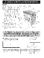
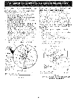
NOTES: 1. Do not pinch the power supply cord between the range and the wall. 2. Do not seal the range to the side cabinets. 213/_" 3.24" (61cm) minimum clearance between the cooktop and the bottom of the cabinet when the bottom of wood or metal - Kenmore 4689 | Installation Instructions - Page 3
) Wide Cooktop. by at least 1/16" (see illustration 2). Illustration 1 Slide the unit into the cabinet. Make sure the center of the unit is aligned . After the installation, MAKE SUREthat the uni is supported by the leveling legs NOT by the cooktop. .-Tosuccessfully install range, the initial - Kenmore 4689 | Installation Instructions - Page 4
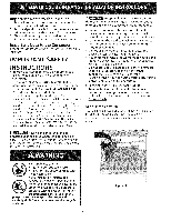
Note to the Consumer Keep these instructions with your owner's guide for future reference. IMPORTANT SAFETY INSTRUCTIONS • Be sure your range is installed and grounded properly by a qualified installer or service technician. • This range must be electrically grounded in accordance with local codes - Kenmore 4689 | Installation Instructions - Page 5
kit. NOTE: Electric Slide-in Range is shipped from factory with 1 1/8" (2.9 cm) dia. hole as shown on figure 4. If a larger hole is required, punch out the knockout. Risk of fire or electrical shock exists if an incorrect size range cord kit is used, the Installation Instructions are not followed - Kenmore 4689 | Installation Instructions - Page 6
rear wire cover (access cover) upward to expose range terminal connection block (see figure 2). 2. Remove SilverColoredTerminal Red .Wire Direct Electrical Connection to the Circuit Breaker Kit Hole. A User Supplied Strain-relief Must Be Installed at This Location To 240 V Receptacle NOTE: Be - Kenmore 4689 | Installation Instructions - Page 7
reduce the 3A" (1.9 cm) dimension. Countertop must be level, installation of the range, but is an added convenience. Connector (or CSA listed) Refer to the Use and Care Guide for NOTE: Be sure to remove the supplied grounding strap. oven door removal instructions. Figure 6 - 4-Wire Electrical - Kenmore 4689 | Installation Instructions - Page 8
raise the unit by lowering the leveling legs. Level the range (see section 6). The floor where he range is to be installed must be level. Follow the instructions under "Leveling the Range-Models Equipped with Leveling Legs". Slide the range into the cutout opening. Make sure that the cooktop glass - Kenmore 4689 | Installation Instructions - Page 9
_ RAISE Figure 8 Models Equipped with Leveling Leg_s the range and set cooktop height before installation in the cut-out opening. 1. Install an oven rack in range, if necessary, by adjusting the 4 leg levelers with a wrench (see Figure 14). 3. Taking care to not damage the countertop, slide range - Kenmore 4689 | Installation Instructions - Page 10
for or making inquiries about your range, always be sure to include the model and serial numbers and a lot number or letter from the serial plate on your range. Before You Call for Service Read the Avoid Service Checklist and operating instructions in your Use and Care Guide. It may save you time - Kenmore 4689 | Installation Instructions - Page 11
| Anti-Tip instructions- Brackets Installation Ceramic Glass Cooktop only Models Equipped with Leveling Device To reduce the risk of tipping of the range, the range must be secured to the floor by properly installed anti-tip bracket and screws packed with the range. Those parts are located in the - Kenmore 4689 | Installation Instructions - Page 12
hot liquids or from the range itself. Follow the instructions below to install the anti-tip brackets. If range is ever moved to a installed with the range. To check for proper installation, see step 5. Tools Required: 5/16" (0,79 cm) Nutdriver or Flat Head Screwdriver Adjustable Wrench Electric - Kenmore 4689 | Installation Instructions - Page 13
o el enchufe de conexion con la tierra deberia situarse de 8" a 17" (20.3 - 43.2 cm) del armario derecho y de 2" a 4" (5.1-10.2 cm) del suelo. No instale la unidad en el gabinete si no ha leido esta pagina. AALTURA (Debajo de la cubierta)) 35 7/8" (91,1 cm)- 36 5/8" (93 cm) B.' ANCHURA €:ANCHURA - Kenmore 4689 | Installation Instructions - Page 14
NOTA: 1. No pellizque el cordon electdco o el conducto gas entre la estufa y la pared. 2. No selle la estufa a los armados de lado. flexible de 3. Un espado minimo de 24" (61 cm) entre la superfide de la estufa y el fondo del armado cuando el fondo del armario de madera o metal est_fl protegido - Kenmore 4689 | Installation Instructions - Page 15
Para evitar fractura de la unidad: NO manipule la unidad sosteniendo la cubierta de vidrio. k La cubierta alrededor del espacio donde usted instalara su uni- _ dad debe de estar plana y nivelada. (Vea el _irea sombreada en la ilustracion n0mero 1). Antes de instalar la unidad, mida la altura de los - Kenmore 4689 | Installation Instructions - Page 16
Limpie todo exceso de derrames. Siga las instrucciones para la pre-limpieza en el Manual del usuario. F_ Nunca deje a los ni_os solos o sin cuidado en el las cocinas pueden inclinarse. Esto puede provocar lesiones personales Instale el dispositivo antiindinacion que viene con la cocina. Para - Kenmore 4689 | Installation Instructions - Page 17
1. Estuche de cable del suministro electrico El utilizador es responsable de la conexiOn del cable del suministro el@ctricoal bloque de conexi6n situado detr_is del panel de acceso. El electrodom_stico se puede conectar a trav_s de un cableado permanente "cableado duro"; cable de cobre blindado - Kenmore 4689 | Installation Instructions - Page 18
Conexion del cable de cuatro conductores a ia cocina. 1. Retire los 3 tornillos de la parte baja de la cubierta del cable trasero, luego levante la cubierta hacia arriba para tener acceso (cubierta de acceso) al bloque de conexi0n del borne terminal (vea figura 2). 2. Retire la correa de la base del - Kenmore 4689 | Installation Instructions - Page 19
y alineados antes de instalar la plancha de cocinar. Lije el horde del mostrador para obtener las 31 1/2 (81 cm)" en la parte superior del mostrador. Instale las puertas del armario a 31 " (78,7 cm) de espacio entre elias para que no interfieran con la abertura de la puerta de la cocina. Corte - Kenmore 4689 | Installation Instructions - Page 20
necesario, levante la unidad bajando las patas de nivelaci6n. Instale el soporte anti=inclinacion de acuerdo alas instrucciones del patron representante Sears. Instaladon con Paneles Laterales Llenos Los Paneles Laterales puede set pedidos con su representante Sears. Instale las puertas - Kenmore 4689 | Installation Instructions - Page 21
3. Verifiquesilacocinaest_nqiveladcaolocandouna parrillaenelcentrodelhomoy poniendounnivel sobreesta(figura9). 4. Midadosvecesconelnivelenposici6ndiagonael n unadirecci6ny luegoenotra.Nivelelacocinasies necesariaojustandolaspatasdenivelaci6n. 5. Sialcocinanosenivelaa, seg0resqeueel pisoeste nivelado - Kenmore 4689 | Installation Instructions - Page 22
o letra del Iote de la placa de serie de su estufa. Antes de Llamar al Servicio Lea la secciOn Evite Llamadas de Servicio en su Manual del Usuario. Esto le podr_i ahorrar tiempo y gasto. Esta lista incluye ocurrencias comunes que no son el resultado de defectos de materiales o fabricaci6n de este - Kenmore 4689 | Installation Instructions - Page 23
Instrucdones de instalad6n de la fijacion anti-inclinacion - Modelos con una cubierta ceramico vidriado Para los modelos equipado con un sistema de dispositivo de nNelad6n. Para reducir el riesgo de inclinaciOn de la cocina, _sta debe ser asegurada hacia el piso con las fijaciones de anti- - Kenmore 4689 | Installation Instructions - Page 24
P_vaerlaadloorsas.modelos equipado con ias Para reducir el riesgo de inclinaciOn de la cocina, _sta debe set asegurada hacia el piso con las fijaciones de anti-inclinaci6n y los tornillos que vienen con la cocina. Estos componentes se encuentran en el homo. Si no instala las fijaciones, corre el
-
 1
1 -
 2
2 -
 3
3 -
 4
4 -
 5
5 -
 6
6 -
 7
7 -
8
-
9
-
10
-
11
-
12
-
13
-
14
-
15
-
16
-
17
-
18
-
19
-
20
-
21
-
22
-
23
-
24
 |
 |

United States
INSTALLATION AND
SERVICE
MUST BE
PERFORMED
BY A QUALIFIED INSTALLER.
IMPORTANT:
SAVE FOR LOCAL
ELECTRICAL
INSPECTOR'S
USE.
READ
AND
SAVE THESE INSTRUCTIONS
FOR FUTURE
REFERENCE.
FOR YOUR SAFETY: Do not store
or use gasoline
or other
flammable
vapors
and liquids
in
the vicinity
of this or any other
appliance.
These
surfaces
should
be flat
& leveled
(hatched
area).
Y2"Mio.
30"
Min.
(76.2cm) Min.
,
(76.2cm) Min. See Note 3)
/
18" Min.
Min.
(45.7cm) Min.
Shave Raised
Edge To Clear
Space for
31 5/16"
(81cm)
Wide
Cooktop
1 1/2" Max.
(3.8cm Max.)
Locate Cabinet
Doors 1" (2.5cm)
Min. From Cutout
Opening
Approx. 1 7/8"
G
(4.8 cm)
F
Grounded
Junction
Box or Wall Outlet
Should
Be
Located
8" to 17"
(20.3 - 43.2
cm) From Right
Cabinet
and 2" to 4" (5.1-10.2
cm) From Floor
24"
Min.
(61cm) Min.
Do not
install
the
unit
in
the
cabinet
before
reading
next
two
pages.
35 7/8"
(91.1cm) -
31 5/16"
28 5/16" (71.9cm)
30_+1/16" (76.2_+0.15cm)
21 3/4"
(55.2cm) Min.
36 5/8" (93cm)
(79.5cm)
22 1/8" (56.2cm) Max
24" (61cm) Min. with
backguard
Printed
in
United
States
36 5/8" (93cm) Max.
35 7/8"
(91.1cm)
P/N 318201617
(0905)
Rev. A
English - pages 1-12
Espahol - p_iginas 13-24