Kenmore 4689 Installation Instructions - Page 5
Power, Supply, Access, to Terminal, Block, Grounding, Strap, Electrical, Connection, to the, Range - electric range
 |
View all Kenmore 4689 manuals
Add to My Manuals
Save this manual to your list of manuals |
Page 5 highlights
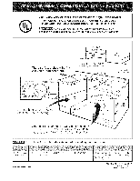
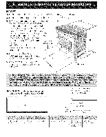
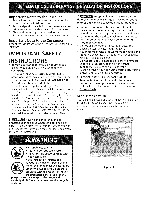
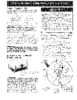
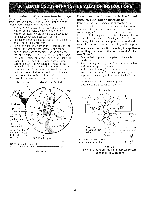
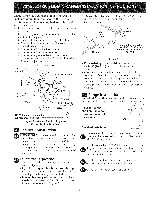
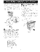
1. Power Supply Cord Kit The user is responsible for connecting the power supply cord to the connection block located behind the back panel access cover. This appliance may be connected by means of permanent "hard wiring"; flexible armored or nonmetallic shielded copper cable (when local code allow it) or by means of a power supply cord kit. NOTE: Electric Slide-in Range is shipped from factory with 1 1/8" (2.9 cm) dia. hole as shown on figure 4. If a larger hole is required, punch out the knockout. Risk of fire or electrical shock exists if an incorrect size range cord kit is used, the Installation Instructions are not followed, or the strain relief bracket is discarded, For mobile homes, new installations or recreational vehicles, use only a power supply kit designed for a range at 125V/250V 50A recommended (minimum 40A). Cord must have either 3 (when local code permits grounding through neutral) or 4 conductors. Terminal on end of wires must be either closed loop or open spade lug with upturned ends. Cord must have strain-relief clamp. Do not loosen the nuts which secure the factory-installed range wiring to terminal block while connecting range. Electrical failure or loss of electrical connection may occur, 2. Access to Terminal Block & Grounding Strap Electrical Shock Hazard o Electrical ground is required on this appliance, Do not connect to the electrical supply until appliance is permanently grounded. Disconnect power to the circuit breaker or fuse box before making the electrical connection, This appliance must be connected to a grounded, metallic, permanent wiring system, or a grounding connector should be connected to the grounding terminal or wire lead on the appliance, Failure to do any of the above could result in a fire, personal injury or electrical shock. 3. Electrical Connection to the Range Three Conductor Wire Connection to Range If local codes permit connection of the frame grounding conductor to the neutral wire of the copper power supply cord (see Figure 3): 1. Remove the 3 screws at the lower end of the rear wire cover, then bend the lower end of the rear wire cover (access cover) upward to expose range terminal connection block (see Figure 2). 2. Using the nuts supplied in the literature package, connect the neutral of the copper power supply cord to the center silver-colored terminal of the terminal block, and connect the other wires to the outer terminals. Match wires and terminals by color (red wires connected to the right terminal, black wires connected to the left terminal) (see figure 3). 3. Lower the terminal cover and replace the 3 screws. Silver Colored Terminal Red Wire Bend rear wire cover here for access to terminal block Figure 2 This appliance is manufactured with the frame grounded by connection of a grounding strap between the neutral power supply terminal and the frame. If used in USA, in a new branch circuit installation (1996 NEC), mobile home or recreational vehicule, where local code do not permit grounding through neutral (white) wire or in Canada; remove the grounding strap from the frame and cut the other end, near the neutral terminal, Connect the appliance in usual manner, Terminal Block Wire A User Supplied Strain-relief Must Be Installed at This Location. To 240 V Receptacle Figure 3 1 1/8" (2.9 cm) Dia. Direct Connection Hole. Punch Out Knockout for 1 3/8" (3.5 cm) Dia. Cord Kit Hole.
-
 1
1 -
 2
2 -
 3
3 -
 4
4 -
 5
5 -
 6
6 -
 7
7 -
 8
8 -
 9
9 -
 10
10 -
 11
11 -
12
-
13
-
14
-
15
-
16
-
17
-
18
-
19
-
20
-
21
-
22
-
23
-
24
 |
 |
