Kenmore 9802 Installation Instructions
Kenmore 9802 - Elite 30 in. Electric Range Manual
 |
View all Kenmore 9802 manuals
Add to My Manuals
Save this manual to your list of manuals |
Kenmore 9802 manual content summary:
- Kenmore 9802 | Installation Instructions - Page 1
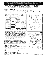
SERVICE MUST BE PERFORMED BY A QUALiFiED TECHNiCiAN. iMPORTANT: SAVE FOR THE LOCAL ELECTRICAL iNSPECTOR'S USE. READ AND SAVE THESE iNSTRUCTiONS FOR FUTURE REFERENCE. 1. Clearances and Dimensions a. Provide adequate clearances between the range Keep these instructions with your Use and Care Guide for - Kenmore 9802 | Installation Instructions - Page 2
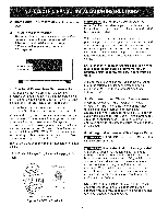
Models Requiring Power Supply Cord Kit l U.S. STYLE Figure 1 - 3=Wire Cord Kit Risk of fire or electrical shock may occur if an incorrect size range cord kit is used, the installation instructions are not followed or strain relief bracket is discarded. This appliance may be connected by means of - Kenmore 9802 | Installation Instructions - Page 3
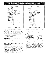
(white) or center wire must be connected to center terminal. D. Reinstall terminal box cover, Do not loosen nuts which secure the factory installed range wiring to terminal block while connecting range. Electrical failure or loss of electrical connection may occur. 7. Wiring Instructions = 4-Wire - Kenmore 9802 | Installation Instructions - Page 4
Call for Service Checklist and operating instructions in your Use and Care Guide. It may save you time and expense. The list includes common occurrences that are not the result of defective workmanship or materials in this appliance. Refer to your Use and Care Guide for Sears service phone numbers - Kenmore 9802 | Installation Instructions - Page 5
"_ 36 + 1/8" '_301/8"_ O"clearance below cooking top and at rear of range. Un minimo de 30" de espacio entre la parte superior de la superficie importantes para el instalador 1. Lea todas las instrucciones contenidas en este manual antes de instalar la estufa. 2. Saque todo el material usado en - Kenmore 9802 | Installation Instructions - Page 6
de conexi6n el6ctrica Este aparato debe estar instalado en forma apropiada y puesto a tierra pot un tecnico calificado, de acuerdo con el National Electric Code (C6digo Nacional de Electricidad) ANSl/NFPA No. 70 --01tima edici6n-- y con los requerimientos de electricidad de los c6digos locales. Este - Kenmore 9802 | Installation Instructions - Page 7
Desde la estufa ..... AIgunos Modelos Caja Terminal de la_stufa Linea 2 ...... Neutro (bianco o central) puesta a tierra Tornillo de puesta tierra .... Abrazadera de prevenci6n de tensi6n ......... Para fusible, desconectar la caja o el instrumento aprobado de alambrado para el cordon de cobre - Kenmore 9802 | Installation Instructions - Page 8
antivuelco encuentran en un saco de pl_stico en el homo. Antes de Ilamar al servicio Lea la secci6n Lista de Antes de Ilamar en su Manual del Usuario. Esto le podrA ahorrar tiempo y gastos. Esta lista incluye ocurrencias comunes que no son el resultado de defectos de materiales o fabricaci6n de
-
 1
1 -
 2
2 -
 3
3 -
 4
4 -
 5
5 -
 6
6 -
 7
7 -
8
 |
 |
iNSTALLATiON
AND
SERVICE
MUST
BE
PERFORMED
BY
A QUALiFiED
TECHNiCiAN.
iMPORTANT:
SAVE
FOR THE
LOCAL
ELECTRICAL
iNSPECTOR'S
USE.
READ
AND
SAVE
THESE
iNSTRUCTiONS
FOR
FUTURE
REFERENCE.
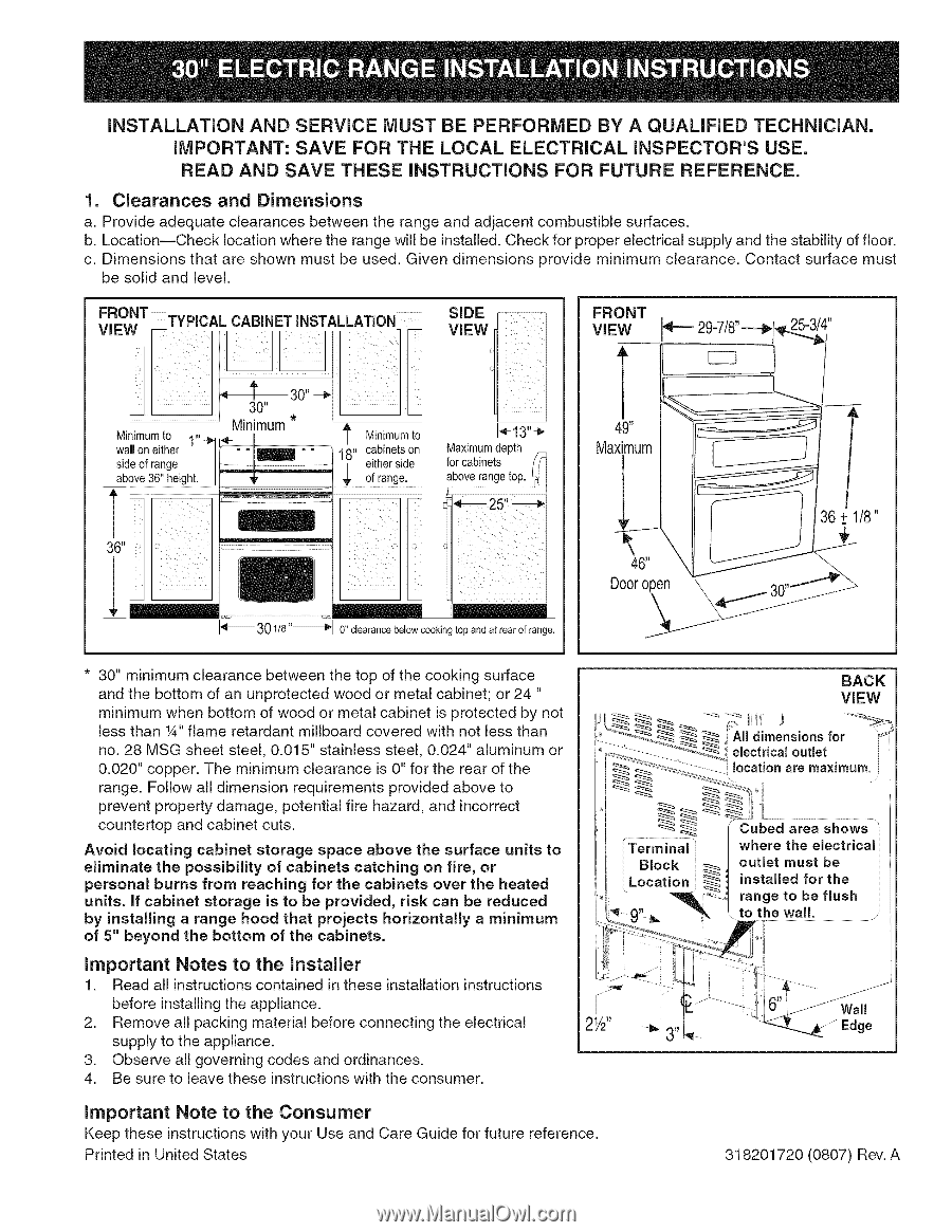
1.
Clearances
and
Dimensions
a. Provide adequate
clearances
between the range and adjacent
combustible
surfaces.
b. Location--Check
location where the range will be installed. Check for proper electrical
supply and the stability of floor.
c. Dimensions
that are shown
must be used. Given dimensions
provide
minimum
clearance.
Contact
surface
must
be solid and level.
FRONT
TYPICAL CABINET
iNSTALLATiON
ViEW
Minimumto
1"
wail on either
-
Pit
side of range
I
I
above 36" height.
I
°
s"#vff
1_13"÷
18"
cabinets on
Maximumdepth
""
either side
for cabinets
f/
_-------
3 01/8
"--------_
O"dearance
below cooking top and at rear of range.
1'
30" --_
I
30"
Minimum
t
Minimumto
FRONT
VIEW
T
49"
l
Maximum
36 ± 1/8"
46'
X
\..
Door
open
"\
30,,.11"v_-_
29-7/8"--._i I
25-3/4"
* 30" minimum
clearance
between the top of the cooking
surface
and the bottom of an unprotected
wood or metal cabinet; or 24 "
minimum
when bottom of wood or metal cabinet
is protected
by not
less than 1A"flame
retardant
millboard
covered
with not less than
no. 28 MSG sheet steel, 0.015" stainless
steel, 0.024" aluminum
or
0.020" copper.
The minimum
clearance
is O"for the rear of the
range. Follow all dimension
requirements
provided above to
prevent property
damage,
potential
fire hazard, and incorrect
countertop
and cabinet cuts.
Avoid
locating
cabinet
storage
space
above
the
surface
units
to
eliminate
the
possibility
of
cabinets
catching
on fire, or
personal
burns
from
reaching
for the cabinets
over
the heated
units.
If cabinet
storage
is
to be
provided,
risk can be reduced
by
installing
a range
hood
that
projects
horizontally
a minimum
of 5" beyond
the bottom
of the cabinets.
Important
Notes
to the
Installer
1.
Read all instructions
contained
in these installation
instructions
before installing the appliance.
2.
Remove
all packing material before connecting the electrical
supply to the appliance.
3.
Observe all governing
codes and ordinances.
4.
Be sure to leave these instructions
with the consumer.
important
Note
to the
Consumer
Keep these instructions with your
Use and Care Guide for future reference.
Printed in United States
BACK
ViEW
_f '-:i:-
...........
__
-_--__o_
electrical outlet
',//_
_-
........
location
are maximum.
•
/
........................
(
Cubed area shows
'
I/
Terminal'_
I where the electricall I
I
Block
[ _/
outlet
must
be
I
Location
.__
installed
for the
',/
'
"_
:'_-_'1range to be flush
I'_- 9' _
_
,, to
the
wall.
/;
o ,o,I
t
"_"
_ 3"_
-_:-__v _
Edge
318201720
(0807) Rev. A