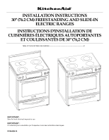
KitchenAid KERS807SBL Installation Instructions - Page 4
Installation Requirements - parts
 |
UPC - 883049027029
View all KitchenAid KERS807SBL manuals
Add to My Manuals
Save this manual to your list of manuals |
Page 4 highlights
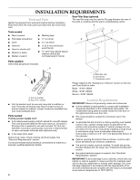
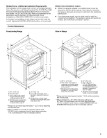
INSTALLATION REQUIREMENTS Tools and Parts Gather the required tools and parts before starting installation. Read and follow the instructions provided with any tools listed here. Tools needed Rear Filler Strip (optional) The rear filler strip may be used to fill a gap between the rear of the slide-in cooktop and the wall in a freestanding cutout. A B ■ Tape measure ■ Masking tape ■ Flat-blade screwdriver ■ Level ■ ¼" nut driver nut driver B C ■ Hammer ■ Hand or electric drill ■ Wrench or pliers ■ Marker or pencil 3.2 mm) drill bit (for wood floors) 4.8 mm) carbide-tipped masonry drill bit (for concrete/ceramic floors) Parts supplied Check that all parts are included. A B A. Anti-tip bracket B. #12 x 1⁵⁄₈" screws ■ Anti-tip bracket must be securely mounted to subfloor or wall. Thickness of flooring may require longer screws to anchor bracket to subfloor. Longer screws are available from your local hardware store. Parts needed If using a power supply cord: ■ A UL listed power supply cord kit marked for use with ranges. The cord should be rated at 250 volts minimum, 40 amps or 50 amps that is marked for use with nominal 1³⁄₈" (3.5 cm) diameter connection opening and must end in ring terminals or open-end spade terminals with upturned ends. ■ A UL listed strain relief. Check local codes. Check existing electrical supply. See "Electrical Requirements" section. It is recommended that all electrical connections be made by a licensed, qualified electrical installer. 4 A. Rear filler strip B. Countertop C. Countertop cutout Please reference the "Assistance or Service" section of the Use and Care Guide to order. Black - W10113902A White - W10113903A Biscuit - W10113904A Location Requirements IMPORTANT: Observe all governing codes and ordinances. ■ It is the installer's responsibility to comply with installation clearances specified on the model/serial rating plate. The model/serial rating plate is located inside the oven door on the right-hand side oven door trim. ■ The range should be located for convenient use in the kitchen. ■ To eliminate the risk of burns or fire by reaching over heated surface units, cabinet storage space located above the surface units should be avoided. If cabinet storage is to be provided, the risk can be reduced by installing a range hood or microwave range hood combination that projects horizontally a minimum of 5" (12.7 cm) beyond the bottom of the cabinets. ■ Cabinet opening dimensions that are shown must be used. Given dimensions are minimum clearances. ■ The anti-tip bracket must be installed. To install the anti-tip bracket shipped with the range, see "Install Anti-Tip Bracket" section. ■ Grounded electrical supply is required. See "Electrical Requirements" section. IMPORTANT: To avoid damage to your cabinets, check with your builder or cabinet supplier to make sure that the materials used will not discolor, delaminate or sustain other damage. This oven has been designed in accordance with the requirements of UL and CSA International and complies with the maximum allowable wood cabinet temperatures of 194°F (90°C).
-
 1
1 -
 2
2 -
 3
3 -
 4
4 -
 5
5 -
 6
6 -
 7
7 -
 8
8 -
 9
9 -
 10
10 -
11
-
12
-
13
-
14
-
15
-
16
-
17
-
18
-
19
-
20
-
21
-
22
-
23
-
24
-
25
-
26
-
27
-
28
 |
 |
