LG GR-K18PBS Service Manual
LG GR-K18PBS Manual
 |
View all LG GR-K18PBS manuals
Add to My Manuals
Save this manual to your list of manuals |
LG GR-K18PBS manual content summary:
- LG GR-K18PBS | Service Manual - Page 1
eLG http://bizigservice.com KIMCHI REFRIGERATOR SERVICE MANUAL CAUTION PLEASE READ CAREFULLY THE SAFETY PRECAUTIONS OF THIS MANUAL BEFORE CHECKING OR OPERATING THE REFRIGERATOR. 10 MODEL : GR-K113PB/GR-K18PBC - LG GR-K18PBS | Service Manual - Page 2
description 9 . freezing cycle refrigerant 7,General details about the 8 Major repair method for freezing cycle 35 - 96 C-haracterlstles-of-eacli-part- Pr 11. Assembly diagram and service parts list 53 - LG GR-K18PBS | Service Manual - Page 3
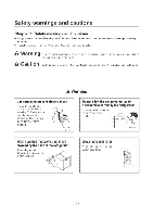
means a dangerous condition which could result in significant damage, injury or death if the instructions are not followed. Caution means a condition which could result in damage or injury if instructions are not followed. A Warning Use caution to prevent electric shock The control panel (main - LG GR-K18PBS | Service Manual - Page 4
Safety warnings and cautions A Warning This product should always be grounded, when needed. If you think that there is a possibility of electricity leakage by water or moisture, always ground the unit. Do not store flammable liquid or gas in the refrigerator such as ether, benzene, alcohol, - LG GR-K18PBS | Service Manual - Page 5
fire or electric shock. r During repairs, remove all dust and foreign material from the housing part, connector part and check part. It can prevent problems such as tracking or short circuit. Allow at least 5 minutes for resetting if you unplug the refrigerator. If can cause an overload to the - LG GR-K18PBS | Service Manual - Page 6
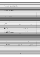
Chapter 2. Product specification Item Usable volume Volume Left compartment Right compartment External dimensions Width Depth Height Total weight power consumption Store/Season Insulation material Fresh Vegetable basket retngerator container ompressor cD Evaporator 0 Refrigerant (amount) 0 - LG GR-K18PBS | Service Manual - Page 7
Product installation method Chapter 3. Product installation method 3-1. Method to adjust height of refrigerator ■ First adjust the level of the refrigerator. (It the floor is uneven, the refrigerator may vibrate or cause noise.) Horizontal adjustment leg (lower handle part) ► Adjust the front to - LG GR-K18PBS | Service Manual - Page 8
Circuit diagram Chapter 4. Circuit diagram CIRCUIT DIAGRAM LED MODULE DISPLAY 91)1 A.IA1 12 345 8K BN RD 80 YL CON101 YL SWAY 2 BO VALVE MOTER 3 4 RD BL J 5 BN 6 BK POWER SUPPLY CORD GNAT RN BN RD BO YL 12 34 5 CONS RD 6 BL 5 YL 4 60 3 BN 2 BK 1 GON4 PWB(PCB) ASSEMBLY, MAIN CON1 - LG GR-K18PBS | Service Manual - Page 9
MICOM function and circuit description Chapter 5. MICOM function and circuit description 5-1. Function description 5-1-1. Display part i • 14MM •0111/21II • 2r aI 91 xi ci 0 gwi • iLllil IMO • Elio Mg* M . Sv. .• tlEnill a*(2*x) • l'inlx1 IM*Jkini •llti i: 7,al l* lm . ty m Bkoltill *el - LG GR-K18PBS | Service Manual - Page 10
5-1-2.Food storage/seasoning fmwtion -(11-When-selecting-fooeFtypeancEstoring temperature 1 Press the ActelttUaltackbutton=for=more than 2-e4orids=to switch to "Unlock" status 2. Press the "StGrer'brittarito-ehange the storing temperature to Mid"- "Max" ) Wirt" -) "Mid". The food type changes - LG GR-K18PBS | Service Manual - Page 11
5-1-3. When selectingpower on/offfunction 1. Press the "Lock/tAtloci&' button for=inote=than 2 seconels4o=evititch to "IJ " 2. Press the "Compartment selection"-bTtitarcti:Eselect th=npartment 3. At this time, press4he=Pewerbutton for mere-than 2 seconds to turn the power off. 4. At this time, - LG GR-K18PBS | Service Manual - Page 12
- LG GR-K18PBS | Service Manual - Page 13
• I • •PEEPPNWENIAHININ ININNI MINIO-PMEIMMI-PAMNI MINIUMWEIMPI-PINVAI-Minamlft. ra Ion m rfsI lase 1 am 1len 1 ra e storagetsenses the ambient=tenveratute and adjusts the temperature in the compartm rage from being too cold or-tee-warm-beeause of seasonal variations and maintains exac partments - LG GR-K18PBS | Service Manual - Page 14
MICOM function and circuit description 5-1-10. Error diagnosis function 1. The error diagnosis function is the function to support SVC in case of an error that can affect the performance of the product. 2. If an error occurs, the control panel button will not work. 3. - LG GR-K18PBS | Service Manual - Page 15
- LG GR-K18PBS | Service Manual - Page 16
5-2. Circuit description 5-2-1. Power circuit ON1 9 lad +12V 111/41S ' t2 • ~14 bi • 44. 11000/AREF) ,46)4SS) WST _The_power_orcutt-consists-ot-the-notse-attenuation part-and tlae-SA4F-S--(-Switch-Mode-Vower-supply)--part_4.be SMPS consists of the rectifier (Rni & CFI) to (Innvprt AC`, - LG GR-K18PBS | Service Manual - Page 17
1V 12V (2) Buzzer delving Circuit (located on display PCB) * Only the buzzer sound for the Lock/Unlock operation is shown in this SVC technical manual. LED MODULE TYPE ; ,033_4191)1_46 ass rf Dom+ 24 P11 (INT1) IC101 (MICUM) P1- 26 P10 (Prim3/rC3iPO03) Status measuring point Ex) Lock: "Ding - LG GR-K18PBS | Service Manual - Page 18
5-2-5. Switchinput circuit itch signal to check the refrigeratflr. P13 0 TEST - I t• it I:I-. iille_sensimkuilL The following temperature-beeeeF circuit consists of a sensor to detect the outside (ambient) temperature and sensors in the fight mpartmentsforstoring and seasoning-Kirnctri - LG GR-K18PBS | Service Manual - Page 19
5-2-7. Stepping motor operation circuit (3-way valve) 11102.5361P -0- A 5 4 .__ com 401.2 9,16 n i- :1-18 Isk ,,1_0K 10K • 10K 3 t 1-3 2 L ,T 1.,51.12.13 'Cl ICOM 111P41(SCL/SI) 5 -P4.1(STOP/11475) p42(soA/so) ► The motor 43--operateci--by-sencing--out-litgri--anci--Low" signals as - LG GR-K18PBS | Service Manual - Page 20
MICOM function and circuit description 5-2-9. Storing temperature compensation and over-cool/under-cool cut compensation circuit (1) Storing temperature compensation RCL Foiv10K RCR 10K R19 R20 10K 10K Y22EY0 fr't Y2STYg 7 P63 (AIN4) 8 P64 (AIN4) IC1 (MID:1M) ► This is the circuit to input - LG GR-K18PBS | Service Manual - Page 21
admen' storm temperature compensation OP/ The cut compensation circuit compensates the storin tem eratUre of the left or right compartment b sim I CUttin it out of service • r* - LG GR-K18PBS | Service Manual - Page 22
5-2-10. Communication circuit between main PCB and display PCB the main MB=artdAhe MICOM of the dis ere Is nn cnrnmnn cs nn between these bnarai fnr RO seconds, a communication error occurs. N PCB DISPLAY PCB ■ GND Send (Err Receive (Notch status) MICOM for LED control PWB(PCB) ASSEMBLY, MAIN - LG GR-K18PBS | Service Manual - Page 23
- LG GR-K18PBS | Service Manual - Page 24
_&3-,%nsar_resistans*-characteristiasiable -Measufing temper -15°C; 0°C +5°C 15°C 20°C +30°C +40°C ht seri 77 Ka 60 Ku 30 KQ 24.1 KC≥ 15 9 MI 13 KS/ 8.9 KO 6.2 KQ CON2 SENSOR 2 (I EN) 1 4 ICI CONS CON101 2 S 5 RT SENSOR In ► The tolerance-ot the-sensorreststance-ts-±3%. lk_Measure testa - LG GR-K18PBS | Service Manual - Page 25
TRAMS D I- O O O 0 DI FBI On • a. O O O O O o RI rc IC3 O O 0 O C05 -1-4A, S0-0 R3 O O J D • O O C7 o III mo OOOOO o• J12 J13 wo 0 14 O D O 0 00001 0000 R33 RIS RI RIS II L2 0 LI 04 O O-4aAt-O • 0 O O OHO S O 44ts1 CI 4-44EO 12 o N 8 UN N N CC CC C•C O O - LG GR-K18PBS | Service Manual - Page 26
,• I ,W •IWINIMINOril-WINWEP INWEINWI MEW-PPW•WWI-Iri=ol 1V/IIM=11T/Mil•laraidraliai+1•TaMa.lIda.1•11:MaF•LI•Nia.lalallIrml• 1'1ILwAw/ lw I • LIP/ • =IP • Iw M'FI I &yaw I IIMw lm-re./.1• 1 Mr•II L.J • mozmozoossrA IMIMMILE MIEWIMMINSM MIIMMEMMINEM MIIMMEMMEMELPMELPMENMERN NIMMIMMIMMIMESEMBEH - LG GR-K18PBS | Service Manual - Page 27
MICOM function and circuit description 54.3. PWB (PCB) assembly and display parts diagram and parts list The parts list can slightly change according to the situation. 0o :-.9, 4 ginwattieotsivaii. ow L.E0 4t Xl i '2- ' :-- 1.4 7. :.U; 1 apisini , It seal uzeir•i• ft -. U4€I• •-• g laiRm e - LG GR-K18PBS | Service Manual - Page 28
- LG GR-K18PBS | Service Manual - Page 29
- LG GR-K18PBS | Service Manual - Page 30
5-5-2. PWB (PCB) assembly and display cretut diagram (6871JB1397) The circuit diagram can slightl tenge according to the situation This includes the PWB (PCB) axsEmbly and sub circuit diagram 1 VooPUIUM PS 1ST 5 Ma. PM I- I I p. I 4.11 .•1 wive I i>c,• wm 2.1•Va o PPP ./C6C "L0, 1.00 !L !L - LG GR-K18PBS | Service Manual - Page 31
Chapter 6. Freezing cycle and refrigerant 6-1-1. Freezing principle F ingis-an-operation of maintaining a-lewer-temperature (generally 0°C) than the natural tcmperaturc (usually ambicn temperature surrounding us). This requires an-insulated-space, refrigerant (R134a) to absorb tho hoa circuit ( - LG GR-K18PBS | Service Manual - Page 32
6-1-3. Operation descriptionofeach circulation circuit No. Parts Cnmprassnr Operation details Cnmprass tha refrigerant from law prassiIra (0kg/cm2) to high pressure 8-12kg/cm2 . Refrigerant gas oondrlion (input and Lnw prassura gas--High prassius OAR /cm2) (8-12kg/cm2) T -1 ` 2 Condenser - LG GR-K18PBS | Service Manual - Page 33
- . Refrigerator no The structure of the freezing room and mechanical room, which are the sources of Klrnchl refrigerator noise, is as foltaws. Here you can see that the main source of noise during refrigerator operation is the compressor, the condenser and the fan motor that cools the compressor in - LG GR-K18PBS | Service Manual - Page 34
for major noise claim item for Kimchi refrigerator Noise claim Noise generation Service method Remarks Noise from poor installation Ili• The installation floor surface is not hard enough Ili. The refrigerator is not leveled • Reinforce the floor hardness • - LG GR-K18PBS | Service Manual - Page 35
- LG GR-K18PBS | Service Manual - Page 36
- LG GR-K18PBS | Service Manual - Page 37
8-3. Caution during major repair Itaem 1. Using tools 2 Removing re - LG GR-K18PBS | Service Manual - Page 38
Major repair method for freezing cycle 8-4. Actual major repair work Item 1. Removing residual refrigerant Low pressure _side, a Caution Evaporator Condenser Drier i High pressure 3iWay side Valve 0 Key Point Maintain refrigerant removing order (Oil can leak from Compressor) Hol Line - LG GR-K18PBS | Service Manual - Page 39
• IMIO-NIMMEMNPIPEIMPIIM4PPMEINUEINEW*1 INIEMMINI sf 4•11WPMF 4•1•PEIMP -I*1•1WINMININWIPEN Iii Virailid*.1.•1.-..Ilia•I*.11•WAY•kitaklirld*LT*.lwAlialaMe-11/a11*. II•IL`FAMW. -lylellMII1. -11•LwA.=L**/ Ia*P -1.*-1 1I•L`rMe -"A NOW't:lei' 1111110 Caution 911=3,71;1•1= p ndenser r71111r - LG GR-K18PBS | Service Manual - Page 40
Item -5. Charging the refrigerant Evaporator Compressor '' Drier Condenser High pressure 3-Way side Valve Hot Line Pipe 4) Charging the refrigerant: As shown above, operate the refrigerant-with the charging pipe. -5) When-lhe-charging is complete, pinch the charging pipe using the pinch- - LG GR-K18PBS | Service Manual - Page 41
8-6. Welding reference diagrgin Evaporator (Left cumpculineill) Accumulator Suctio Evaporator (Right compartment) Mr' BII Hnt I ine Pipe \3-Way Valve per o 0 O Condenser Welding classification opper LOKRING Applied parts 11 18 19 Remarks - LG GR-K18PBS | Service Manual - Page 42
8-7. Problem checking procedure Compressor rotates Check the rotation of compressor right side cooler is cold i Wall is Normal Slightly Moisture clogged Poor operation of 3-way valve - LG GR-K18PBS | Service Manual - Page 43
dilet VACnnm nnri RAM refrigerant Cumpleite 8-8-2.3-Way valve service Because the--3-warvalue-eontrols- the- refrigerant with an heat _transmission (below=1:Kee4 (Type with a joint pipe) 2) Valve eynhange senute4valve problem) You must do the-seFvfee-epeFation in the same method as above Body- - LG GR-K18PBS | Service Manual - Page 44
forth movement type) C J Piston 00 Motor part _ Motor supporting spring Lubricant Compressor is composed of the piston part compressing the pipe connected to the external heat emitter. Caution ► The compressor for service is supplied with nitrogen gas charged and the rubber cap sealed. This - LG GR-K18PBS | Service Manual - Page 45
9-1-2. Overload protection relay (O.L.P) structure and function • The overload protection relay cuts=the power to protest the motor when the temperature of the compressor rises abnormal when the overly high-cur-rent is sent to the-compressor motor. • Overload protection relay structure is composed - LG GR-K18PBS | Service Manual - Page 46
Characteristics of each part 9-1-4. Refrigerant valve (1) Function This switches the refrigerant that went through the compressor to the left or right compartment evaporator. COMP Compressor .... ,.. .., Refrigerant valve r ---- DRIER Suction pipe Evaporator CAPILLARY TUBE (Left - LG GR-K18PBS | Service Manual - Page 47
(3) Operating principle Controlling the rotating angle-of the step valve connected to-ti4e-bettem-et-04e rotor e compartment open (STEP .0) Closed area or will open/close the outlet pipe entrance by changing the shag-ef-the ig compartment-L-efflight compartment Left compa men open open ( - LG GR-K18PBS | Service Manual - Page 48
9-1-5. Motor (mechanical room) This is the partused-feEcirculating the air within the mechanical room and applies te4he-wire condenser type. This operates when the-compressor opera and the heated refrigerant from the compressor-lowers the-temperature when passing through the wire condenser_ancialso - LG GR-K18PBS | Service Manual - Page 49
arac ens ics oT earn par • Operating principle Where the AD power ib cormected to the cod of the Shading pole motor, the central axis-of the magnetic field-shifts-in the bold arrow direct s the Mlfral awi5a=rnoves, the rotor moves rn the bdUle dneclwn tU tUIll t le MOM. Why doestecceentral - LG GR-K18PBS | Service Manual - Page 50
lex Lest) or Kinrclri seasvrsrly Resistance value Remarks (Applicable to Poor product Poorteatar • Hcatcr asscmbly (fcrmcnt/ricc storagc) Problem (dame) yrtip ulTi _t_. Heat wire disconnected/connecliff0- _wire disconnected 2. Poor terminal contact- K' 'l not seasoned Check method 1. Measure - LG GR-K18PBS | Service Manual - Page 51
and the basic structure is as shown in the right figure. (3) Poor symptom (product) A electrode - - 17 Dielectric material B electrode Problem (parts) Symptom ❑isconnected (open) Shorted Normal 1) Compressor does not work. 2) Compressor is heated. 3) OLP is operating. 4) Power fuse is - LG GR-K18PBS | Service Manual - Page 52
. be-eareful-net-te-apply=twaTtach pressure damage-thirPWB (PCB) assem,ly. display or make scratches on frame display and ease-U. Depending °nitre-mode, the service slot is on the top left or right side. rame 'spay ase- - LG GR-K18PBS | Service Manual - Page 53
parts list Chapter 11. Assembly diagram and service parts list 11-1. Assembly diagram (GR-K18PB/GR-K18PBC) 230A 200A 233A 261C 281B 200B 221A 281E 233A 281D 230B 203B 243A 604A 604B 501A 4 - LG GR-K18PBS | Service Manual - Page 54
Assembly diagram and service parts list 249G 249D 249B 212D (270t) 1 248A 4CD 410H - LG GR-K18PBS | Service Manual - Page 55
11-2. Service mils list (GR-K18PB/GR-K18PBC) 102A LEGADJU 147A BANK,SIDE DISH 147C COVER ASSEMBLY.BANK 200A I)X1Bine+M AS. ) -200B DOOR FOAM ASSEMBLY.R P03A GASKET. - LG GR-K18PBS | Service Manual - Page 56
LOCNo. DESCRIPTION 320A HOLDER, BRACKET -323B CONDENSER ASSEMBLY WIRE -927A RUBBER,MOTOR-N 32/B RUBBER, DAMPING -329C FAN ASSEMBLY 4108 HOLDER,CAPACITOR 410C CAPAuron,n 410H CAPACITOR,MS 411A POWER CORD ASSEMBLY 501A PWB(PCB) AS,EMBLY,MAIN _502B CASE ASSEMBLYPWB -004A-DEODORIZER 604B COVER - LG GR-K18PBS | Service Manual - Page 57
LG Electronics Inc. P/No. 3828JD8935A SEP., 2005 Printed in Korea
-
 1
1 -
 2
2 -
 3
3 -
 4
4 -
 5
5 -
 6
6 -
 7
7 -
8
-
9
-
10
-
11
-
12
-
13
-
14
-
15
-
16
-
17
-
18
-
19
-
20
-
21
-
22
-
23
-
24
-
25
-
26
-
27
-
28
-
29
-
30
-
31
-
32
-
33
-
34
-
35
-
36
-
37
-
38
-
39
-
40
-
41
-
42
-
43
-
44
-
45
-
46
-
47
-
48
-
49
-
50
-
51
-
52
-
53
-
54
-
55
-
56
-
57
 |
 |

eLG
http://bizigservice.com
KIMCHI
REFRIGERATOR
SERVICE
MANUAL
CAUTION
PLEASE
READ
CAREFULLY
THE
SAFETY
PRECAUTIONS
OF
THIS
MANUAL
BEFORE
CHECKING
OR
OPERATING
THE
REFRIGERATOR.
10
MODEL
:
GR-K113PB/GR-K18PBC