LG HBLG1003R Service Manual - Page 11
Service Manual, Installation
 |
View all LG HBLG1003R manuals
Add to My Manuals
Save this manual to your list of manuals |
Page 11 highlights
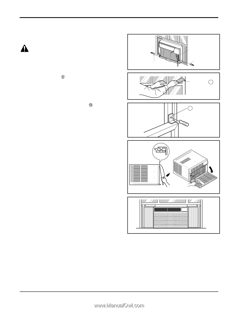
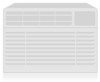
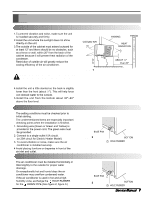
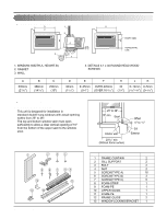
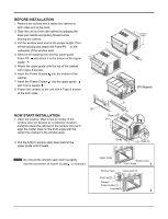
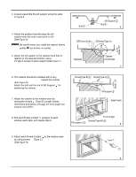
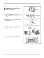
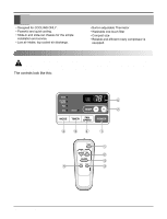
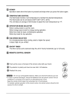
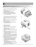
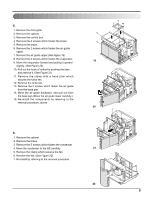
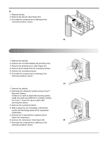
10. Slide the unit into the cabinet.(See Fig. 10) CAUTION: For security purpose, reinstall screws (Type A) at cabinet's sides. 11. Cut the Foam-Strip to the proper length and insert between the upper and lower window sash. (See Fig. 11) 12. Attach the window Locking Bracket with a type C screw. (See Fig. 12) 13. Attach the front grille to the cabinet by inserting the tabs on the grille into the tabs on the front of the cabinet. Push the grille in until it snaps into place.(See Fig. 13) Installation Screw(Type A) Power cord Screw(Type A) Figure 10 Foam-Strip 8 Figure 11 13 Figure 12 14. Lift the inlet grille and secure it with a type A screw through the front grille.(See Fig. 14) Figure 13 Figure 14 COOL FAN DRY HEAT DEFROST FAN INDOOR DESIRED ENERGY SAVER AIR PURYFIER AUTO RESTART Figure 15 Service Manual 11
-
 1
1 -
2
-
3
-
4
-
5
-
 6
6 -
 7
7 -
 8
8 -
 9
9 -
 10
10 -
 11
11 -
 12
12 -
 13
13 -
 14
14 -
 15
15 -
 16
16 -
17
-
18
-
19
-
20
-
21
-
22
-
23
-
24
-
25
-
26
-
27
-
28
-
29
-
30
-
31
-
32
-
33
-
34
-
35
-
36
-
37
-
38
-
39
-
40
-
41
 |
 |