LG LWHD1000R Service Manual
LG LWHD1000R Manual
 |
View all LG LWHD1000R manuals
Add to My Manuals
Save this manual to your list of manuals |
LG LWHD1000R manual content summary:
- LG LWHD1000R | Service Manual - Page 1
website http://www.lgservice.com LG LG Room Air Conditioner SERVICE MANUAL MODEL: LWHD8000R,LWHD8000RY5,LWHD1000R,LWHD8000RY6 CAUTION • BEFORE SERVICING THE UNIT, READ THE SAFETY PRECAUTIONS IN THIS MANUAL. • ONLY FOR AUTHORIZED SERVICE PERSONNEL. - LG LWHD1000R | Service Manual - Page 2
Air Conditioner Service Manual TABLE OF CONTENTS Safety Precautions...3 Dimensions ...6 Outside Dimensions ...6 Product Specifications ...7 Installation ...8 Select the Best Location ...8 Installation Check ...8 How to Secure the Drain Pipe ...8 How to Install...9 Operation ...12 Function of - LG LWHD1000R | Service Manual - Page 3
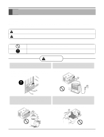
s Meanings of symbols used in this manual are as shown below. Be sure not to do. Be sure to follow the instruction. WARNING Always install the expansion panel(s). Do not place the power cord near a heater. • Improper assembly or installation may cause incorrect operation, including injury, fire - LG LWHD1000R | Service Manual - Page 4
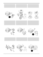
cause electric shock or fire. ON Do not damage or use an unspecified power cord. • It will cause electric shock or fire. ON Do not modify power cord length. • It will cause electric shock or fire. Use the air conditioner on a single outlet circuit. Do not share the outlet with other appliances - LG LWHD1000R | Service Manual - Page 5
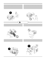
. • If the outer case is damaged, it must be repaired or replaced immediately. Leaving it damaged could result in the air conditioner falling out of the window, creating a safety hazard. Be cautious not to touch the sharp edges when installing. • It may cause injury. Sharp edges Service Manual 5 - LG LWHD1000R | Service Manual - Page 6
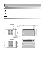
Dimensions Dimensions Symbols Used in this Manual This symbol alerts you to the risk of electric shock. This symbol alerts you to hazards that could cause harm to the air conditioner. NOTICE This symbol indicates special notes. Outside Dimensions 30 (1 3/16") 492 (19 3/8") 42 (1 21/32") 100.3 (3 - LG LWHD1000R | Service Manual - Page 7
Product Specifications Specfications ITEMS MODELS POWER SUPPLY CAPACITY (BTU/h) INPUT (W) FAN MOTOR OPERATION CONTROL ROOM TEMP. CONTROL AIR DIRECTION CONTROL CONSTRUCTION PROTECTOR COMPRESSOR FAN MOTOR POWER CORD DRAIN SYSTEM NET WEIGHT OUTSIDE DIMENSION x 492 Service Manual 7 - LG LWHD1000R | Service Manual - Page 8
or Green and Yellow) is provided in the power cord. The green wire must be grounded. 2. Connect to a single-outlet 15A circuit. (or 20A circuit for Electric Heater Model) 3. To avoid vibration or noise, make sure the air conditioner is installed securely. 4 Avoid placing furniture or draperies in - LG LWHD1000R | Service Manual - Page 9
MOUNTED ON Installation HARDWARE TYPE A: 11EA (SHORT SCREW) TYPE B: 5EA (WOOD SCREW) TYPE C: 3EA (L BACKET) DRAIN PIPE 10mm 16mm TYPE D: 1EA (SEAL STRIP) (Adhesive backed) TYPE E: 1EA (SASH SEAL) (Not adhesive backed) TYPE F: 2EA (GUIDE PANEL) TYPE G: 1EA (SUPPORT BACKET) Service Manual - LG LWHD1000R | Service Manual - Page 10
Figure 7 INNER SILL OUTER SILL TYPE A INSIDE CENTER LINE 3. INSTALL THE AIR CONDITIONER IN THE WINDOW a. Carefully lift the air conditioner and slide it into the open window. Make sure the bottom guide of the air conditioner drops into the notches of the L bracket. See Figure. 8. IMPORTANT - LG LWHD1000R | Service Manual - Page 11
on the air conditioner, raise the sash, and carefully tilt the air conditioner backward, draining any condensate water. Lift the air conditioner from the window ad remove the sash seal from between the windows. L Bracket Type A Type B Figure 11 Installation Sash Seal (Type F) Service Manual 11 - LG LWHD1000R | Service Manual - Page 12
Operation Operation • Designed for COOLING ONLY. • Powerful and quiet cooling. • Top-down chassis for the simple instal- lation and service. • Low air-intake, top cooled-air discharge. Function of Controls • Built-in adjustable Thermistor • Washable one-touch filter • Compact size • Equipped with - LG LWHD1000R | Service Manual - Page 13
power cord. Mechanical Parts 1. Front Grille 1. Open the lnlet grille downward and remove the air . 4. Remove the cabinet. 5. Re-install the components by referring to the removal the 1 screw which fasten the power cord. 4. Disconnect the grounding screw 12. Re-install the components by referring to - LG LWHD1000R | Service Manual - Page 14
the fan. (See Figure 17) 7. Re-install by referring to the removal procedure. 6. Shroud 1. Remove the fan. (Refer to section 2.2.2) 2. Remove the shroud. (See Figure 18) 3. Re-install the components by referring to the removal procedure, above. 14 Room Air Conditioner Figure 15 Figure 16 Figure 17 - LG LWHD1000R | Service Manual - Page 15
top cover from the control box. (See Figure 21) 3. Pull out the capacitor from the control box. 4. Disconnect all the leads of capacitor terminals. 5. Re-install the components by referring to the removal procedure, above. Disassembly Figure 19 Figure 20 Figure 21 Service Manual 15 - LG LWHD1000R | Service Manual - Page 16
from the capacitor and relay. 5. Pull out the power cord. 6. Re-install the component by referring to the above removal procedure, above air guide. (See Figure 23) 5. Remove the motor. 6. Re-install the components by referring to the removal procedure, above.(See Figure 23) 16 Room Air Conditioner - LG LWHD1000R | Service Manual - Page 17
the condenser. 6. Re-install the components by referring to notes. (See Figure 23) 13. Evaporator 1. Remove the control box.(Refer to section 3) 2. Remove the air guide upper. (Refer to Figure 24 3. Remove the capillary tube. 4. Re-install the components by referring to notes. Service Manual 17 - LG LWHD1000R | Service Manual - Page 18
there is no valve to attach the recovery system, install one (such as a WATCO A-1) before venting the FreonTM. Leave the valve in place after servicing the system. 2. After discharging the unit completely, remove while, and then test the leakage of the pinch-off connection. 18 Room Air Conditioner - LG LWHD1000R | Service Manual - Page 19
, Brazing equipment. Pin-off tool capable of making a vapor-proof seal, Leak detector, Tubing cutter, Hand Tools to remove components, Service valve. CONDENSER (HIGH PRESSURE SIDE) COMPOUND GAUGE MANIFOLD GAUGE B A CAPILLARY TUBE SEE INSETS BELOW EVAPORATOR (LOW PRESSURE SIDE) COMPRESSOR - LG LWHD1000R | Service Manual - Page 20
Schematic Diagram Schematic Diagram Electronic Control Device 20 Room Air Conditioner 09AV 11 33 55 77 99 CN-PWR YW396-03AV 33 11 Model Cool Only Heat Pump RY-4WAY RY-4WAY X O J07 CN- ) ANGLE RY-COMP G4A-1A-E-LG ZNR01J SVC271D-14A SVC271D-14A FUSE 250VT3.15A POWER TRANS 1 7 D02D D05D 2 - LG LWHD1000R | Service Manual - Page 21
Schematic Diagram 1 BK CN-MOTOR CN-AC/DC CN-AC/DC GN/YL BL 5 (GN) MOTOR RD YL DC PCB OR ASSEMBLY RY-LOW RY-MED RY-HI CAPACITOR CN-TH1 YL 2 F POWER 8 PLASMA FILTER ASSY S: Service Parts N: Non Service Parts Q'TY PER SET 1 1 1 1 1 1 1 1 REMARKS S S S S S S S S Service Manual 21 - LG LWHD1000R | Service Manual - Page 22
Schematic Diagram Components Location 1. MAIN P.C.B ASSEMBLY CN-CON J1 CN-AC/DC CN-12V CN-4WAY C01J E03J E02J E01J J8 RY-4WAY RY-COMP ASSEMBLY:6871A20417C POWER TRANS FUSE 250V/T3.15A E04J E05J 2. DISPLAY P.C.B. ASSEMBLY PCB:6870A90067C ASSEMBLY:6871A20418A 22 Room Air Conditioner - LG LWHD1000R | Service Manual - Page 23
ROOM AIR HEAT LOAD CONDENSER COILS VAPOR INLET HOT DISCHARGED AIR LIQUID PRESSURE DROP MOTOR OUTSIDE COOLING AIR FOR REFRIGERANT PASS THROUGH COMPRESSOR OIL (LIQUID REFRIGERANT) CAPILLARY TUBE Figure 26 LIQUID OUTLET HIGH PRESSURE VAPOR LIQUID REFRIGERANT LOW PRESSURE VAPOR Service Manual 23 - LG LWHD1000R | Service Manual - Page 24
Troubleshooting Guide Troubleshooting Guide In general, possible trouble is classified in two kinds. The one is called Starting Failure which is caused from an electrical defect, and the other is ineffective Air Conditioning caused by a defect in the refrigeration circuit and improper application. - LG LWHD1000R | Service Manual - Page 25
Fails to Start Troubleshooting Guide Check of power source. Check of control switch setting. Compressor only fails to start. Drop of power voltage. Defect of compressor capacitor. (Motor damaged) Regular but fails to start. Replacement of compressor (locking of rotor, metal). Service Manual 25 - LG LWHD1000R | Service Manual - Page 26
Troubleshooting Guide Electrical Parts Troubleshooting Guide Possible Trouble 1 The unit does not operate. Is the NO Trans input power AC 115V? YES Is the Trans output power NO about AC 14V? YES Is output Voltage YES Replace AC PCB Ass'y. • Check the PCB pattern. 26 Room Air Conditioner - LG LWHD1000R | Service Manual - Page 27
Possible Trouble 2 The compressor does not operate. Troubleshooting Guide Is setting Temp. set lower Does the Unit delay for 3 minutes? YES • Wait 3 Minutes. • Replace MAIN PCB Ass'y. Possible Trouble 3 The compressor always operate. Is the wire connection of NO RY-COMP OK? YES • Check the - LG LWHD1000R | Service Manual - Page 28
pushed once more from cool mode? YES Is the voltage No.3 of NO CN-AC/DC of AC PCB Ass'y DC 5V? YES • Reference to OWNER'S MANUAL. • Set the mode key to Energy Saver mode. • Check the Energy Saver mode key. • Check the pattern of AC & DC PCB. 28 Room Air Conditioner - LG LWHD1000R | Service Manual - Page 29
YES Is the connection of NO CN-AC/DC OK? YES • Replace Receiver Ass'y. Troubleshooting Guide • Replace the battery. ••CChheecckkththeePPCCBBppaattteterrnn.. • Connect connector to CN-AC/DC exactly. Possible Trouble 7 It displays abnormally on DC PCB Ass'y. NO Is IC01G good? YES NO Is the - LG LWHD1000R | Service Manual - Page 30
Troubleshooting Guide Electrical Parts Possible Trouble 1 The unit does not operate. Is the NO Trans input power AC 115V? YES Is the Trans output power NO about AC 14V? YES Is output Voltage of IC01D NO DC 5V? YES Replace AC PCB Ass'y. • Check the PCB pattern. 30 Room Air Conditioner - LG LWHD1000R | Service Manual - Page 31
Possible Trouble 2 The compressor does not operate. Troubleshooting Guide Is desired Temp. set lower Is the Unit for 3 minutes delay? YES • Wait 3 Minutes. • Replace AC PCB Ass'y. Possible Trouble 3 The compressor always operate. Is the wire connection of NO RY-COMP OK? YES • Check the - LG LWHD1000R | Service Manual - Page 32
Troubleshooting Guide Possible Trouble 4 FAN does not operate. Is the voltage NO.1 or 2 or 4 NO of IC01M DC 5V? YES Is the voltage NO.16 or 15 or 13 NO of IC01M 0V? YES • Check the RY-Hi or RY-Med or RY-Lo. • Check the wiring diagram. Possible Trouble to CN-AC/DC exactly. 32 Room Air Conditioner - LG LWHD1000R | Service Manual - Page 33
the connection of NO CN-AC/DC OK? YES Does the IC03G NO operate normally on AC PCB Ass'y? YES • Replace the DC PCB Ass'y. Troubleshooting Guide • Replace IC01G, IC02G. • Connect connector to CN-AC/DC exactly. • Replace IC03G. Service Manual 33 - LG LWHD1000R | Service Manual - Page 34
Troubleshooting Guide COMPLAINT Fan motor will not run. Fan motor runs intermittently Fan motor noise. Compressor will not run, but fan motor runs. CAUSE No power Power base, shim up the bottom of the fan motor with mounting screw(s). Check fan motor bearings; if motor shaft will not Air Conditioner - LG LWHD1000R | Service Manual - Page 35
replace the compressor. Check the compressor overload, if externally mounted. Replace if open. (If the compressor temperature is high air guide, rearrange the air handling parts. Remove the cabinet carefully and rearrange tubing not to contact cabinet, compressor, shroud, and barrier. Service Manual - LG LWHD1000R | Service Manual - Page 36
352380-2 159830 135303 135312 349001-2 349001-1 130411 W0CZZ 268711-2 135500 349480 567502 554160 249950 550140 352115 552113 552102 238310 567480 264110 352113 35211A 36 Room Air Conditioner - LG LWHD1000R | Service Manual - Page 37
GUIDE ASSEMBLY 354212 EVAPORATOR ASSEMBLY,FIRST 554030 CONDENSER ASSEMBLY,FIRST 550140 ANTI-VIBRATION BUSH 554160 COMPRESSOR SET 559010 FAN, AXIAL 359012 FAN, TURBO 267110 REMOTE CONTROLLER ASSEMBLY W48602 CLAMP, SPRING W0CZZ CAPACITOR, DRAWING Replacement Parts List PART NO. LWHD8000RY5 LWHD1000R - LG LWHD1000R | Service Manual - Page 38
,Box Power Cord Assembly Thermistor,NTC Escutcheon Cabinet Assembly,Single Guide Remote Controller Assembly Install Part Assembly,Single Frame Assembly Frame Assembly Grille Assembly,Front Grille,Inlet Filter Assembly,Air Cleaner Louver,Horizontal Louver,Vertical Louver,Vertical 38 Service Manual - LG LWHD1000R | Service Manual - Page 39
P/NO:3828A29003C January, 2005 Printed in China
-
 1
1 -
 2
2 -
 3
3 -
 4
4 -
 5
5 -
 6
6 -
 7
7 -
8
-
9
-
10
-
11
-
12
-
13
-
14
-
15
-
16
-
17
-
18
-
19
-
20
-
21
-
22
-
23
-
24
-
25
-
26
-
27
-
28
-
29
-
30
-
31
-
32
-
33
-
34
-
35
-
36
-
37
-
38
-
39
 |
 |

LG
Room
Air Conditioner
SERVICE MANUAL
LG
CAUTION
website http://www.lgservice.com
• BEFORE SERVICING THE UNIT, READ THE SAFETY
PRECAUTIONS IN THIS MANUAL.
• ONLY FOR AUTHORIZED SERVICE PERSONNEL.
MODEL: LWHD8000R,LWHD8000RY5,LWHD1000R,LWHD8000RY6