LG LWHD1000R Service Manual - Page 13
Disassembly - parts
 |
View all LG LWHD1000R manuals
Add to My Manuals
Save this manual to your list of manuals |
Page 13 highlights
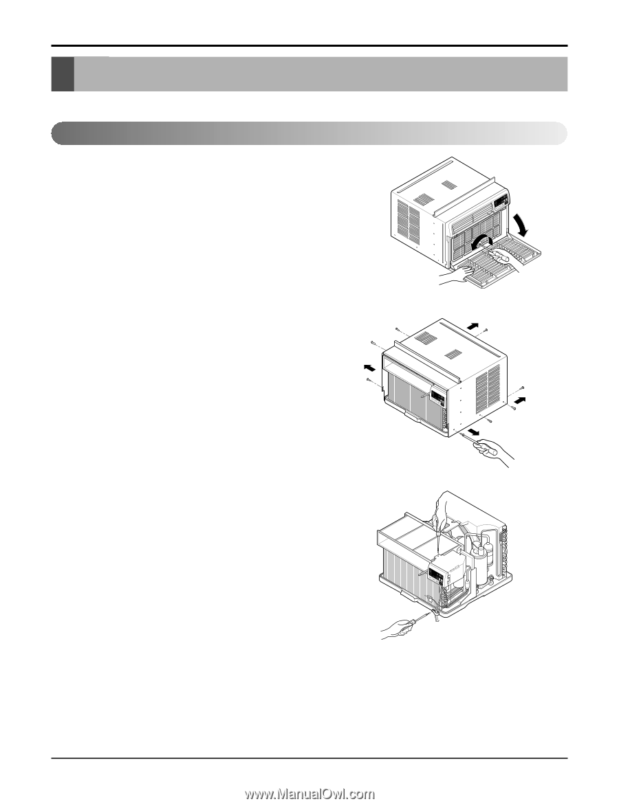
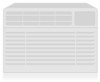
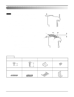
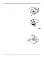
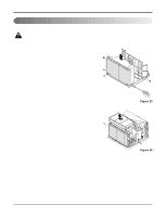
Disassembly Disassembly - Before the following disassembly, set the CONTROL BOX to OFF and disconnect the power cord. Mechanical Parts 1. Front Grille 1. Open the lnlet grille downward and remove the air filter. 2. Remove the screw that fastens the front grille.(See Figure 12) 3. Pull the front grille from the right side. 4. Remove the front grille.(There are 4 hooks.) 5. Re-install the components by referring to the removal procedure, above. 2. Cabinet 1. After disassembling the FRONT GRILLE, remove the 6 screws that fasten the cabinet at both sides. 2. Remove the 2 screws that fasten the cabinet at back. 3. Lift the cabinet from the unit. 4. Remove the cabinet. 5. Re-install the components by referring to the removal procedure, above. Figure 12 3. Control Box 1. Remove the front grille. (Refer to section 1) 2. Remove the cabinet. (Refer to section 2) 3. Remove the 1 screw which fasten the power cord. 4. Disconnect the grounding screw from the evaporator channel. 5. Remove the 2 screws that fastens the control box cover. 6. Remove the housing that connects PCB and motor wire in the control box. 7. Remove the nut that fastens the terminal cover. 8. Remove the terminal cover. 9. Remove all the leads from the overload protector. 10. Discharge the capacitor by placing a 20,000 ohm resistor across the capacitor terminals. 11. Raise the control box upward completely. (See Figure 14) 12. Re-install the components by referring to the removal procedure, above. (Refer to the wiring diagram found on page 21 in this manual and on the control box.) Figure 13 Figure 14 Service Manual 13
-
 1
1 -
2
-
3
-
4
-
5
-
6
-
7
-
 8
8 -
 9
9 -
 10
10 -
 11
11 -
 12
12 -
 13
13 -
 14
14 -
 15
15 -
 16
16 -
 17
17 -
 18
18 -
19
-
20
-
21
-
22
-
23
-
24
-
25
-
26
-
27
-
28
-
29
-
30
-
31
-
32
-
33
-
34
-
35
-
36
-
37
-
38
-
39
 |
 |