Lenovo 25002XU User Manual - Page 195
Then make sure that the right side, LCD unit into the main LCD rear cover
 |
View all Lenovo 25002XU manuals
Add to My Manuals
Save this manual to your list of manuals |
Page 195 highlights
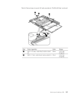
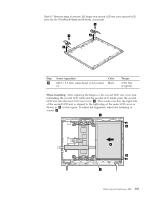
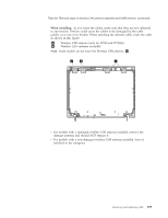
Table 57. Removal steps of second LCD hinges and second LCD rear cover (second LCD cover kit) (for ThinkPad W700ds and W701ds) (continued) 3 3 4 4 Step 3 Screw (quantity) M2.5 × 3.5 mm, wafer-head, nylon-coated (2) Color Black Torque 0.392 Nm (4 kgfcm) When installing: After replacing the hinges or the second LCD rear cover and reinstalling the second LCD cable and the second LCD panel, press the second LCD unit into the main LCD rear cover a . Then make sure that the right side of the second LCD unit is aligned to the right edge of the main LCD cover as shown in b in this figure. To adjust the alignment, adjust the fastening of screws c . c b a b c Removing and replacing a FRU 187
-
 1
1 -
2
-
3
-
4
-
5
-
6
-
7
-
8
-
9
-
10
-
11
-
12
-
13
-
14
-
15
-
16
-
17
-
18
-
19
-
20
-
21
-
22
-
23
-
24
-
25
-
26
-
27
-
28
-
29
-
30
-
31
-
32
-
33
-
34
-
35
-
36
-
37
-
38
-
39
-
40
-
41
-
42
-
43
-
44
-
45
-
46
-
47
-
48
-
49
-
50
-
51
-
52
-
53
-
54
-
55
-
56
-
57
-
58
-
59
-
60
-
61
-
62
-
63
-
64
-
65
-
66
-
67
-
68
-
69
-
70
-
71
-
72
-
73
-
74
-
75
-
76
-
77
-
78
-
79
-
80
-
81
-
82
-
83
-
84
-
85
-
86
-
87
-
88
-
89
-
90
-
91
-
92
-
93
-
94
-
95
-
96
-
97
-
98
-
99
-
100
-
101
-
102
-
103
-
104
-
105
-
106
-
107
-
108
-
109
-
110
-
111
-
112
-
113
-
114
-
115
-
116
-
117
-
118
-
119
-
120
-
121
-
122
-
123
-
124
-
125
-
126
-
127
-
128
-
129
-
130
-
131
-
132
-
133
-
134
-
135
-
136
-
137
-
138
-
139
-
140
-
141
-
142
-
143
-
144
-
145
-
146
-
147
-
148
-
149
-
150
-
151
-
152
-
153
-
154
-
155
-
156
-
157
-
158
-
159
-
160
-
161
-
162
-
163
-
164
-
165
-
166
-
167
-
168
-
169
-
170
-
171
-
172
-
173
-
174
-
175
-
176
-
177
-
178
-
179
-
180
-
181
-
182
-
183
-
184
-
185
-
186
-
187
-
188
-
189
-
 190
190 -
 191
191 -
 192
192 -
 193
193 -
 194
194 -
 195
195 -
 196
196 -
 197
197 -
 198
198 -
 199
199 -
 200
200 -
201
-
202
-
203
-
204
-
205
-
206
-
207
-
208
-
209
-
210
-
211
-
212
-
213
-
214
-
215
-
216
-
217
-
218
-
219
-
220
-
221
-
222
-
223
-
224
-
225
-
226
-
227
-
228
-
229
-
230
-
231
-
232
-
233
-
234
-
235
-
236
-
237
-
238
-
239
-
240
-
241
-
242
-
243
-
244
-
245
-
246
-
247
-
248
-
249
-
250
-
251
-
252
-
253
-
254
-
255
-
256
-
257
-
258
-
259
-
260
-
261
-
262
-
263
-
264
 |
 |

Table 57. Removal steps of second LCD hinges and second LCD rear cover (second LCD
cover kit) (for ThinkPad W700ds and W701ds) (continued)
3
4
4
3
Step
Screw (quantity)
Color
Torque
±3²
M2.5
×
3.5 mm, wafer-head, nylon-coated
(2)
Black
0.392 Nm
(4 kgfcm)
When installing:
After replacing the hinges or the second LCD rear cover and
reinstalling the second LCD cable and the second LCD panel, press the second
LCD unit into the main LCD rear cover
±a²
. Then make sure that the right side
of the second LCD unit is aligned to the right edge of the main LCD cover as
shown in
±b²
in this figure. To adjust the alignment, adjust the fastening of
screws
±c²
.
b
b
a
c
c
Removing and replacing a FRU
187