Lenovo 2518F5U User Manual - Page 151
right edges covered with metal gently with your fingers. DO NOT press
 |
View all Lenovo 2518F5U manuals
Add to My Manuals
Save this manual to your list of manuals |
Page 151 highlights
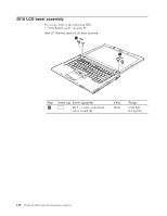
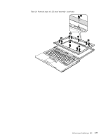
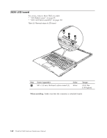
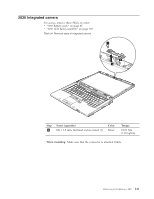
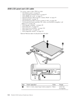
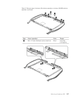
Table 35. Removal steps of LCD panel and LCD cable (continued) 6 7 6 6 7 6 Step 6 Screw (quantity) M2 × 3 mm, wafer-head, nylon-coated (4) Color Black Torque 0.181 Nm (1.85 kgfcm) When installing: When attaching the LCD panel to the cover, press the left and right edges covered with metal gently with your fingers. DO NOT press the surface of the panel or apply any excessive force to the panel. 9 8 When installing: Make sure that the connector is attached firmly. Removing and replacing a FRU 143
-
 1
1 -
2
-
3
-
4
-
5
-
6
-
7
-
8
-
9
-
10
-
11
-
12
-
13
-
14
-
15
-
16
-
17
-
18
-
19
-
20
-
21
-
22
-
23
-
24
-
25
-
26
-
27
-
28
-
29
-
30
-
31
-
32
-
33
-
34
-
35
-
36
-
37
-
38
-
39
-
40
-
41
-
42
-
43
-
44
-
45
-
46
-
47
-
48
-
49
-
50
-
51
-
52
-
53
-
54
-
55
-
56
-
57
-
58
-
59
-
60
-
61
-
62
-
63
-
64
-
65
-
66
-
67
-
68
-
69
-
70
-
71
-
72
-
73
-
74
-
75
-
76
-
77
-
78
-
79
-
80
-
81
-
82
-
83
-
84
-
85
-
86
-
87
-
88
-
89
-
90
-
91
-
92
-
93
-
94
-
95
-
96
-
97
-
98
-
99
-
100
-
101
-
102
-
103
-
104
-
105
-
106
-
107
-
108
-
109
-
110
-
111
-
112
-
113
-
114
-
115
-
116
-
117
-
118
-
119
-
120
-
121
-
122
-
123
-
124
-
125
-
126
-
127
-
128
-
129
-
130
-
131
-
132
-
133
-
134
-
135
-
136
-
137
-
138
-
139
-
140
-
141
-
142
-
143
-
144
-
145
-
 146
146 -
 147
147 -
 148
148 -
 149
149 -
 150
150 -
 151
151 -
 152
152 -
 153
153 -
 154
154 -
 155
155 -
 156
156 -
157
-
158
-
159
-
160
-
161
-
162
-
163
-
164
-
165
-
166
-
167
-
168
-
169
-
170
-
171
-
172
-
173
-
174
-
175
-
176
-
177
-
178
-
179
-
180
-
181
-
182
-
183
-
184
-
185
-
186
-
187
-
188
-
189
-
190
-
191
-
192
-
193
-
194
-
195
-
196
-
197
-
198
-
199
-
200
-
201
-
202
-
203
-
204
 |
 |

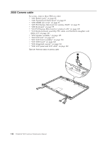
Table 35. Removal steps of LCD panel and LCD cable (continued)
6
6
7
7
6
6
Step
Screw (quantity)
Color
Torque
±6²
M2
×
3 mm, wafer-head, nylon-coated (4)
Black
0.181 Nm
(1.85 kgfcm)
When installing:
When attaching the LCD panel to the cover, press the left and
right edges covered with metal gently with your fingers. DO NOT press the
surface of the panel or apply any excessive force to the panel.
8
9
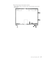
When installing:
Make sure that the connector is attached firmly.
Removing and replacing a FRU
143