Lenovo 7515-J9U User Guide - Page 36
Do not touch the thermal grease while handling the heat sink and fan, from the microprocessor.
 |
UPC - 884942137211
View all Lenovo 7515-J9U manuals
Add to My Manuals
Save this manual to your list of manuals |
Page 36 highlights
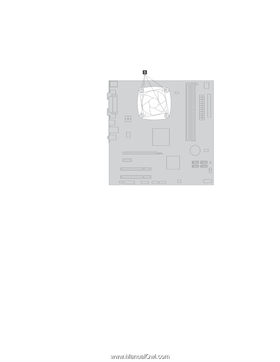
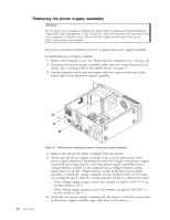
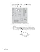
5. Remove the four screws 1 that secure the heat sink and fan assembly to the system board. Note: Carefully remove the four screws from the system board to avoid any possible damage. The four screws cannot be removed from the heat sink and fan assembly. Figure 18. Removing the heat sink and fan assembly 6. Lift the failing heat sink and fan assembly off the system board. Notes: a. You might have to gently twist the heat sink and fan assembly to free it from the microprocessor. b. Do not touch the thermal grease while handling the heat sink and fan assembly. 7. Position the new heat sink and fan assembly on the system board so that the four screws are aligned with the holes on the system board. Note: Position the new heat sink and fan assembly so that the heat sink and fan assembly cable is toward the microprocessor fan connector on the system board. 28 User Guide
-
 1
1 -
2
-
3
-
4
-
5
-
6
-
7
-
8
-
9
-
10
-
11
-
12
-
13
-
14
-
15
-
16
-
17
-
18
-
19
-
20
-
21
-
22
-
23
-
24
-
25
-
26
-
27
-
28
-
29
-
30
-
 31
31 -
 32
32 -
 33
33 -
 34
34 -
 35
35 -
 36
36 -
 37
37 -
 38
38 -
 39
39 -
 40
40 -
 41
41 -
42
-
43
-
44
-
45
-
46
-
47
-
48
-
49
-
50
-
51
-
52
-
53
-
54
-
55
-
56
-
57
-
58
-
59
-
60
-
61
-
62
-
63
-
64
-
65
-
66
-
67
-
68
-
69
-
70
-
71
-
72
-
73
-
74
-
75
-
76
-
77
-
78
-
79
-
80
-
81
-
82
-
83
-
84
-
85
-
86
-
87
-
88
-
89
-
90
-
91
-
92
 |
 |