Lenovo 7515-J9U User Guide - Page 39
handle to secure the new microprocessor in the socket.
 |
UPC - 884942137211
View all Lenovo 7515-J9U manuals
Add to My Manuals
Save this manual to your list of manuals |
Page 39 highlights
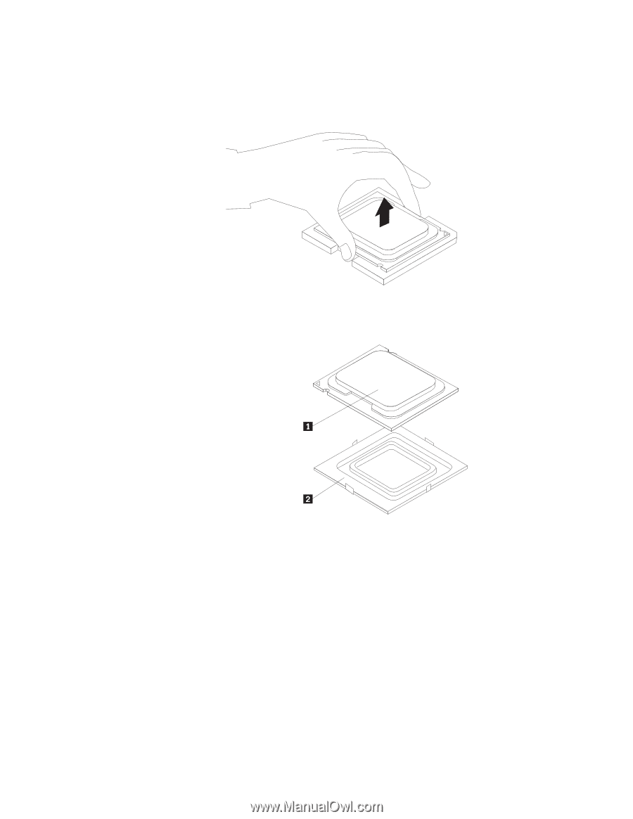
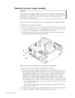
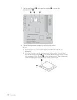
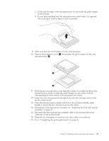
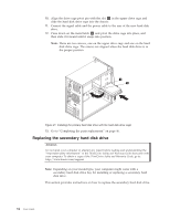
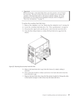
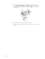
c. Touch only the sides of the microprocessor. Do not touch the gold contacts on the bottom. d. Do not drop anything onto the microprocessor socket while it is exposed. The socket pins must be kept as clean as possible. 9. Make sure that the small handle is in the raised position. 10. Remove the protective cover 2 that protects the gold contacts on the new microprocessor 1 . 11. Hold the new microprocessor and align the notches on it with the tabs in the microprocessor socket, or align the small triangle on one corner with the corresponding beveled corner of the microprocessor socket. 12. Lower the new microprocessor straight down into the microprocessor socket on the system board. 13. Close the microprocessor retainer and lock it into position with the small handle to secure the new microprocessor in the socket. 14. Reinstall the heat sink and fan assembly. See "Replacing the heat sink and fan assembly" on page 27. 15. Reconnect the heat sink and fan assembly cable to the microprocessor fan connector on the system board. 16. Reinstall any other parts or reconnect any other cables you removed. 17. Go to "Completing the parts replacement" on page 46. Chapter 2. Installing options and replacing hardware 31
-
 1
1 -
2
-
3
-
4
-
5
-
6
-
7
-
8
-
9
-
10
-
11
-
12
-
13
-
14
-
15
-
16
-
17
-
18
-
19
-
20
-
21
-
22
-
23
-
24
-
25
-
26
-
27
-
28
-
29
-
30
-
31
-
32
-
33
-
 34
34 -
 35
35 -
 36
36 -
 37
37 -
 38
38 -
 39
39 -
 40
40 -
 41
41 -
 42
42 -
 43
43 -
 44
44 -
45
-
46
-
47
-
48
-
49
-
50
-
51
-
52
-
53
-
54
-
55
-
56
-
57
-
58
-
59
-
60
-
61
-
62
-
63
-
64
-
65
-
66
-
67
-
68
-
69
-
70
-
71
-
72
-
73
-
74
-
75
-
76
-
77
-
78
-
79
-
80
-
81
-
82
-
83
-
84
-
85
-
86
-
87
-
88
-
89
-
90
-
91
-
92
 |
 |