Lenovo IdeaPad V360 Lenovo IdeaPad V360 Hardware Maintenance Manual V2.0
Lenovo IdeaPad V360 Manual
 |
View all Lenovo IdeaPad V360 manuals
Add to My Manuals
Save this manual to your list of manuals |
Lenovo IdeaPad V360 manual content summary:
- Lenovo IdeaPad V360 | Lenovo IdeaPad V360 Hardware Maintenance Manual V2.0 - Page 1
IdeaPad V360 Hardware Maintenance Manual - Lenovo IdeaPad V360 | Lenovo IdeaPad V360 Hardware Maintenance Manual V2.0 - Page 2
using this information and the product it supports, be sure to read the general information under "Notices" on page 82. First Edition (March 2010) © Copyright Lenovo 2010. All rights reserved. LENOVO products, data, computer software, and services have been developed exclusively at private expense - Lenovo IdeaPad V360 | Lenovo IdeaPad V360 Hardware Maintenance Manual V2.0 - Page 3
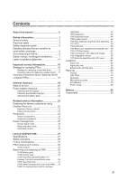
blank mode 25 Sleep (standby) mode 25 Hibernation mode 26 Lenovo IdeaPad V360 27 Specifications 27 Status indicators 29 Fn key combinations 31 FRU replacement notices 32 Screw notices 32 Removing and replacing an FRU 33 1010 Battery pack 34 1020 Dummy card 35 1030 Hard disk drive(HDD - Lenovo IdeaPad V360 | Lenovo IdeaPad V360 Hardware Maintenance Manual V2.0 - Page 4
following Lenovo IdeaPad product: Lenovo IdeaPad V360 Use this manual to troubleshoot problems. The manual is divided into the following sections: •• The common sections provide general information, guidelines, and safety information required for servicing computers. •• The product-specific section - Lenovo IdeaPad V360 | Lenovo IdeaPad V360 Hardware Maintenance Manual V2.0 - Page 5
presents the following safety information that you need to get familiar with before you service an IdeaPad V360 computer: •• "General safety" on page 2 •• "Electrical safety" on page 3 •• "Safety inspection guide" on page 5 •• "Handling devices that are sensitive to electrostatic discharge" on page - Lenovo IdeaPad V360 | Lenovo IdeaPad V360 Hardware Maintenance Manual V2.0 - Page 6
IdeaPad V360 Hardware Maintenance Manual . Do not attempt to lift any object that weighs more than 16 kg (35 lb) or that you think is too heavy for you. in a safe place, keeping them away from all personnel, while you are servicing the machine. •• Keep your toolcase away from walk areas so that other - Lenovo IdeaPad V360 | Lenovo IdeaPad V360 Hardware Maintenance Manual V2.0 - Page 7
from grounds such as metal floor strips and machine frames. Observe the special safety precautions when you work with very high voltages; instructions for these precautions are in the safety sections of maintenance information. Be extremely careful when you measure the high voltages. •• Regularly - Lenovo IdeaPad V360 | Lenovo IdeaPad V360 Hardware Maintenance Manual V2.0 - Page 8
IdeaPad V360 Hardware Maintenance Manual •• Always look carefully for possible hazards in your work The surface is conductive; such touching can cause personal injury and machine damage. •• Do not service the following parts with the power on when they are removed from their normal operating places - Lenovo IdeaPad V360 | Lenovo IdeaPad V360 Hardware Maintenance Manual V2.0 - Page 9
, required safety items were installed to protect users and service personnel from injury. This guide addresses only those items. You should use good judgment to identify potential safety hazards according to the attachment of non-Lenovo IdeaPad features or options not covered by this inspection - Lenovo IdeaPad V360 | Lenovo IdeaPad V360 Hardware Maintenance Manual V2.0 - Page 10
IdeaPad V360 Hardware Maintenance Manual Handling devices that are sensitive to electrostatic discharge Any Select a grounding system, such as those listed below, to provide protection that meets the specific service requirement. Note: The use of a grounding system to guard against ESD damage is - Lenovo IdeaPad V360 | Lenovo IdeaPad V360 Hardware Maintenance Manual V2.0 - Page 11
Safety information Safety notices: multilingual translations The safety notices in this section are provided in English, French, German, Hebrew, Italian, Japanese, and Spanish. Safety notice 1 Before the computer is powered on after FRU replacement, make sure all screws, springs, and other small - Lenovo IdeaPad V360 | Lenovo IdeaPad V360 Hardware Maintenance Manual V2.0 - Page 12
IdeaPad V360 Hardware Maintenance Manual Safety notice 2 DANGER Some standby batteries contain a small amount of nickel and cadmium. Do not disassemble a standby battery, recharge it, throw it into fire or water, or shortcircuit it. Dispose of the battery as required by local ordinances or - Lenovo IdeaPad V360 | Lenovo IdeaPad V360 Hardware Maintenance Manual V2.0 - Page 13
, veillez à n'utiliser que les modèles cités dans la liste de pièces détachées adéquate. En effet, une batterie inappropriée risque de prendre feu ou d'exploser. Akkus enthalten geringe Mengen von Nickel. Sie dürfen nicht zerlegt, wiederaufgeladen, kurzgeschlossen, oder Feuer oder Wasser ausgesetzt - Lenovo IdeaPad V360 | Lenovo IdeaPad V360 Hardware Maintenance Manual V2.0 - Page 14
IdeaPad V360 Hardware Maintenance Manual Safety notice 4 DANGER The lithium battery can cause a fire, an explosion, or a severe burn. Do not recharge it, remove its polarized connector, disassemble it, heat it above 100°C (212°F), incinerate it, - Lenovo IdeaPad V360 | Lenovo IdeaPad V360 Hardware Maintenance Manual V2.0 - Page 15
Safety information Safety notice 5 If the LCD breaks and the fluid from inside the LCD gets into your eyes or on your hands, immediately wash the affected areas with water at least for 15 minutes. Seek medical care if any symptoms caused by the fluid are present after washing. Si le panneau d' - Lenovo IdeaPad V360 | Lenovo IdeaPad V360 Hardware Maintenance Manual V2.0 - Page 16
IdeaPad V360 Hardware Maintenance Manual Safety notice 6 DANGER To avoid shock, do not remove the plastic cover , um brennbare Materialien zu entzünden oder Verletzungen bei Personen hervorzurufen. Sebbene le batterie di alimentazione siano a basso voltaggio, una batteria in corto circuito o a massa - Lenovo IdeaPad V360 | Lenovo IdeaPad V360 Hardware Maintenance Manual V2.0 - Page 17
Safety information Safety notice 8 DANGER Before removing any FRU, turn off the computer, unplug all power cords from electrical outlets, remove the battery pack, and then disconnect any interconnecting cables. Avant de retirer une unité remplaçable en clientèle, mettez le système hors tension, dé - Lenovo IdeaPad V360 | Lenovo IdeaPad V360 Hardware Maintenance Manual V2.0 - Page 18
IdeaPad V360 Hardware Maintenance Manual Laser compliance statement Some models of Lenovo IdeaPad to the requirements of the Department of Health and Human Services 21 Code of Federal Regulations (DHHS 21 CFR) Subchapter di procedure diverse da quelle specificate possono provocare l'esposizione a. - Lenovo IdeaPad V360 | Lenovo IdeaPad V360 Hardware Maintenance Manual V2.0 - Page 19
Safety information A CD-ROM drive, a DVD-ROM drive, or any other storage device installed may contain an embedded Class 3A or Class 3B laser diode. Note the following: DANGER Emits visible and invisible laser radiation when open. Do not stare into the beam, do not view directly with optical - Lenovo IdeaPad V360 | Lenovo IdeaPad V360 Hardware Maintenance Manual V2.0 - Page 20
FRUs listed in this manual. After a system board is replaced, ensure that the latest BIOS is loaded to the system board before completing the service action. To download software fixes, drivers, and BIOS, follow the steps below: 1. Go to http://consumersupport.lenovo.com/. 2. Enter a serial number - Lenovo IdeaPad V360 | Lenovo IdeaPad V360 Hardware Maintenance Manual V2.0 - Page 21
information Use the following strategy to prevent unnecessary expense for replacing and servicing FRUs: •• If you are instructed to replace an FRU, but the replacement does not solve the problem, reinstall the original FRU before you continue. •• Some computers have both a processor board and - Lenovo IdeaPad V360 | Lenovo IdeaPad V360 Hardware Maintenance Manual V2.0 - Page 22
IdeaPad V360 Hardware Maintenance Manual Important information about replacing RoHS compliant FRUs RoHS, The Restriction compliance well before the implementation date and expects its suppliers to be ready to support Lenovo's requirements and schedule in the EU. Products sold in 2005 and 2006 will - Lenovo IdeaPad V360 | Lenovo IdeaPad V360 Hardware Maintenance Manual V2.0 - Page 23
, saving, or formatting. Drives in the computer that you are servicing sequence might have been altered. If you select an incorrect drive, , electrostatic discharge, or software errors. Consider replacing an FRU only when a problem recurs. If you suspect that an FRU is defective, clear the error logs - Lenovo IdeaPad V360 | Lenovo IdeaPad V360 Hardware Maintenance Manual V2.0 - Page 24
IdeaPad V360 Hardware Maintenance Manual What to do first When you do return an FRU, you must include the following information in the parts exchange form or parts return form that you attach to it: 1. Name and phone number of servicer 2. Date of service . Before checking problems with the computer - Lenovo IdeaPad V360 | Lenovo IdeaPad V360 Hardware Maintenance Manual V2.0 - Page 25
adapter pin No. 2 may differ from the one you are servicing. 3. If the voltage is not correct, replace the AC adapter. 4. If the voltage is acceptable, do the following: •• Replace the system board. •• If the problem continues, go to "Lenovo IdeaPad V360" on page 27. Note: Noise from the AC adapter - Lenovo IdeaPad V360 | Lenovo IdeaPad V360 Hardware Maintenance Manual V2.0 - Page 26
IdeaPad V360 Hardware Maintenance Manual Perform operational charging. If the battery status indicator or icon does not light on, remove the battery pack and let it return to room temperature. Reinstall the battery pack. If the charge indicator or icon is still off, replace the battery pack. If the - Lenovo IdeaPad V360 | Lenovo IdeaPad V360 Hardware Maintenance Manual V2.0 - Page 27
the factory contents by using OneKey Recovery Restore of factory default The IdeaPad V360 computers come with pre-installed OneKey Rescue System. In order to save application files and the initial backed up files of the system, the hard disk in a Lenovo computer includes a hidden partition when it - Lenovo IdeaPad V360 | Lenovo IdeaPad V360 Hardware Maintenance Manual V2.0 - Page 28
IdeaPad V360 Hardware Maintenance Manual When you use the recovery discs to boot your computer, the system will enter the user interface for system recovery automatically. Please follow the prompt to insert the backup discs to complete the whole recovery process. Note: The recovery process might - Lenovo IdeaPad V360 | Lenovo IdeaPad V360 Hardware Maintenance Manual V2.0 - Page 29
Related service information Power management Note: Power management modes are not supported for APM operating system. To reduce within that time. •• If the battery indicator is amber, indicating that the battery power is low. (Alternatively, if Hibernate when battery becomes low has been selected in - Lenovo IdeaPad V360 | Lenovo IdeaPad V360 Hardware Maintenance Manual V2.0 - Page 30
IdeaPad V360 Hardware Maintenance Manual Hibernation mode In hibernation mode, the following occurs: •• The system status, RAM, VRAM, and setup data are stored on the hard disk. •• The system is - Lenovo IdeaPad V360 | Lenovo IdeaPad V360 Hardware Maintenance Manual V2.0 - Page 31
table lists the specifications of the Lenovo IdeaPad V360 : Table 1. Specifications Feature Processor Core Chipset Bus architecture Graphic memory chip Display Standard memory CMOS RAM Hard disk drive Description • Intel Calpella i7-620M (2.66GHz 1066MHz) • Intel Calpella i5-520M (2.40GHz 1066MHz - Lenovo IdeaPad V360 | Lenovo IdeaPad V360 Hardware Maintenance Manual V2.0 - Page 32
IdeaPad V360 Hardware Maintenance Manual Table 1. Specifications (continued) Feature I/O port MODEM slot Audio Video Ethernet (on the system board) PCI Express Mini Card slot ExpressCard slot WLAN WWAN Bluetooth wireless Keyboard Touch pad Fingerprint reader Integrated camera Battery & WiMax combo - Lenovo IdeaPad V360 | Lenovo IdeaPad V360 Hardware Maintenance Manual V2.0 - Page 33
Lenovo IdeaPad V360 Status indicators The system status indicators below show the computer status: 12 4 3 5 9 678 Table 2. Status indicators Indicator 1 Drive in use 2 Scroll lock 3 Num lock 4 Caps lock 5 Graphics status (specific models only) 6 Power on Meaning White: Data is being read from - Lenovo IdeaPad V360 | Lenovo IdeaPad V360 Hardware Maintenance Manual V2.0 - Page 34
IdeaPad V360 Hardware Maintenance Manual Table 2. Status indicators (continued) Indicator 7 Battery status 8 Wireless status 9 Touchpad Meaning Blinking amber: (500ms off/1s on) The remaining power of the battery is less than 5% of its capacity. Blinking amber: (100ms off/3.2s on) The battery - Lenovo IdeaPad V360 | Lenovo IdeaPad V360 Hardware Maintenance Manual V2.0 - Page 35
Lenovo IdeaPad V360 Fn key combinations The following table shows the function of each combination of Fn with a function key. Table 4. Fn key combinations Key combination Fn + Esc: - Lenovo IdeaPad V360 | Lenovo IdeaPad V360 Hardware Maintenance Manual V2.0 - Page 36
IdeaPad V360 Hardware Maintenance Manual FRU replacement notices This section presents notices related to removing and replacing parts. Read this section carefully before replacing any FRU. Screw notices Loose screws can cause a reliability problem. In the Lenovo IdeaPad computer, this problem driver - Lenovo IdeaPad V360 | Lenovo IdeaPad V360 Hardware Maintenance Manual V2.0 - Page 37
Lenovo IdeaPad V360 Removing and replacing an FRU This section presents exploded figures with the instructions to indicate how to remove and replace the FRU. Make sure to observe the following general rules: 1. Do not attempt to service electrical outlets, remove the battery pack, and then disconnect - Lenovo IdeaPad V360 | Lenovo IdeaPad V360 Hardware Maintenance Manual V2.0 - Page 38
IdeaPad V360 Hardware Maintenance Manual 1010 Battery pack DANGER Only use the battery specified in the parts list for your computer. Any other battery could ignite or explode. Figure 1. Removal steps of battery pack Unlock the battery release lever 1. Holding the battery release lever in the - Lenovo IdeaPad V360 | Lenovo IdeaPad V360 Hardware Maintenance Manual V2.0 - Page 39
Lenovo IdeaPad V360 1020 Dummy card For access, remove this FRU: •• "1010 Battery pack" on page 34 Figure 2. Removal steps of dummy card Remove the dummy card in the direction shown by arrows 1 2. 1 2 35 - Lenovo IdeaPad V360 | Lenovo IdeaPad V360 Hardware Maintenance Manual V2.0 - Page 40
IdeaPad V360 Hardware Maintenance Manual 1030 Hard disk drive(HDD)/Mini PCI Express Card slot compartment cover For access, remove this FRU: •• "1010 Battery pack" on page 34 Figure 3. Removal steps of Hard disk drive(HDD)/Mini PCI Express Card slot compartment cover Loosen two screws 1, but do not - Lenovo IdeaPad V360 | Lenovo IdeaPad V360 Hardware Maintenance Manual V2.0 - Page 41
Lenovo IdeaPad V360 1040 Hard disk drive For access, remove these FRUs in order: •• "1010 Battery pack" on page 34 •• "1030 Hard disk drive(HDD)/Mini PCI Express Card slot compartment cover" on page 36 Attention: • Do not drop the hard - Lenovo IdeaPad V360 | Lenovo IdeaPad V360 Hardware Maintenance Manual V2.0 - Page 42
IdeaPad V360 Hardware Maintenance Manual 1050 DIMM compartment cover and DIMM For access, remove this FRU: •• "1010 Battery pack" on page 34 Figure 5. Removal steps of DIMM compartment cover and DIMM Loosen one screw 1, but do not remove it. Remove the DIMM compartment - Lenovo IdeaPad V360 | Lenovo IdeaPad V360 Hardware Maintenance Manual V2.0 - Page 43
Lenovo IdeaPad V360 Figure 5. Removal steps of DIMM compartment cover and DIMM (continued) Release the two latches on both edges of the socket at the same time in - Lenovo IdeaPad V360 | Lenovo IdeaPad V360 Hardware Maintenance Manual V2.0 - Page 44
IdeaPad V360 Hardware Maintenance Manual 1060 PCI Express Mini Card for wireless LAN/WAN For access, remove these FRUs in order: •• "1010 Battery pack" on page 34 •• "1030 Hard disk drive(HDD)/Mini PCI Express Card slot compartment cover" on page 36 Figure 6. Removal steps of PCI Express - Lenovo IdeaPad V360 | Lenovo IdeaPad V360 Hardware Maintenance Manual V2.0 - Page 45
Lenovo IdeaPad V360 Figure 6. Removal steps of PCI Express Mini Card for wireless LAN/WAN (continued) Remove two cards in the direction shown by arrows 3. 3 3 When installing: •• In - Lenovo IdeaPad V360 | Lenovo IdeaPad V360 Hardware Maintenance Manual V2.0 - Page 46
IdeaPad V360 Hardware Maintenance Manual 1070 Keyboard For access, remove this FRU: •• "1010 Battery pack" on page 34 Figure 7. Removal steps of keyboard Remove one screw 1. 1 Step 1 Screw (quantity) M2.5 × 8 mm, flat-head, nylok-coated (1) Color Black Torque 3.0 kgfcm 42 - Lenovo IdeaPad V360 | Lenovo IdeaPad V360 Hardware Maintenance Manual V2.0 - Page 47
Lenovo IdeaPad V360 Figure 7. Removal steps of keyboard (continued) Lift the keyboard a little 2, and then detach the connector in the direction shown by arrows 3 4. 2 3 4 When installing: Make sure that the FPC connector is attached firmly. 43 - Lenovo IdeaPad V360 | Lenovo IdeaPad V360 Hardware Maintenance Manual V2.0 - Page 48
IdeaPad V360 Hardware Maintenance Manual 1080 Keyboard bezel For access, remove these FRUs in order: •• "1010 Battery pack" on page 34 •• "1070 Keyboard" on page 42 Figure 8. Removal steps of keyboard bezel Remove nine screws 1 on the bottom. 1 1 1 1 1 1 1 1 1 Step 1 Screw (quantity) M2.5 × 8 - Lenovo IdeaPad V360 | Lenovo IdeaPad V360 Hardware Maintenance Manual V2.0 - Page 49
Lenovo IdeaPad V360 Figure 8. Removal steps of keyboard bezel (continued) Remove three screws 2, 3. 2 3 2 Step 2 3 Screw (quantity) M2.5 × 6 mm, flat-head, nylok-coated (2) M2.5 × 4 mm, flat-head, nylok-coated (1) Color White Black Torque 3.0 kgfcm 3.0 kgfcm 45 - Lenovo IdeaPad V360 | Lenovo IdeaPad V360 Hardware Maintenance Manual V2.0 - Page 50
IdeaPad V360 Hardware Maintenance Manual Figure 8. Removal steps of keyboard bezel (continued) Detach four FPC connectors in the direction shown by arrows 4 5. Unplug the microphone connector in the direction shown - Lenovo IdeaPad V360 | Lenovo IdeaPad V360 Hardware Maintenance Manual V2.0 - Page 51
Lenovo IdeaPad V360 Figure 8. Removal steps of keyboard bezel (continued) Remove the keyboard bezel in the direction shown by arrow 6. 6 Remove two screws 7 and then remove the power - Lenovo IdeaPad V360 | Lenovo IdeaPad V360 Hardware Maintenance Manual V2.0 - Page 52
IdeaPad V360 Hardware Maintenance Manual 1090 System board Important notices for handling the system such as an ESD mat or conductive corrugated material. For access, remove these FRUs in order: •• "1010 Battery pack" on page 34 •• "1020 Dummy card" on page 35 •• "1030 Hard disk drive(HDD)/Mini - Lenovo IdeaPad V360 | Lenovo IdeaPad V360 Hardware Maintenance Manual V2.0 - Page 53
Lenovo IdeaPad V360 Figure 9. Removal steps of system board Remove two screws 1, and detach the LCD connector, speaker connectors and bluetooth connector in the direction shown by arrows 2. 1 2 1 2 2 2 - Lenovo IdeaPad V360 | Lenovo IdeaPad V360 Hardware Maintenance Manual V2.0 - Page 54
IdeaPad V360 Hardware Maintenance Manual Figure 9. Removal steps of system board (continued) Remove the system board in the direction shown by arrow 3. 3 b b a a When installing: When attaching the system board to - Lenovo IdeaPad V360 | Lenovo IdeaPad V360 Hardware Maintenance Manual V2.0 - Page 55
Lenovo IdeaPad V360 1100 Fan assembly and Heat Sink assembly For access, remove these FRUs in order: •• "1010 Battery pack" on page 34 •• "1020 Dummy card" on page 35 •• "1030 Hard disk drive(HDD)/Mini PCI Express Card slot compartment cover" on page 36 •• " - Lenovo IdeaPad V360 | Lenovo IdeaPad V360 Hardware Maintenance Manual V2.0 - Page 56
IdeaPad V360 Hardware Maintenance Manual Figure 10. Removal steps of fan assembly and heat sink assembly (continued) Loosen five screws 2, but do not remove them. 2 2 21 21 2 52 - Lenovo IdeaPad V360 | Lenovo IdeaPad V360 Hardware Maintenance Manual V2.0 - Page 57
Lenovo IdeaPad V360 Figure 10. Removal steps of fan assembly and heat sink assembly (continued) Lift the fan assembly and heat sink assembly in the direction shown by - Lenovo IdeaPad V360 | Lenovo IdeaPad V360 Hardware Maintenance Manual V2.0 - Page 58
IdeaPad V360 Hardware Maintenance Manual Figure 10. Removal steps of fan assembly and heat part shown in the figure above. Either too much or too less grease application can cause a thermal problem due to imperfect contact with a component. In models with the discrete graphics chip, there is an - Lenovo IdeaPad V360 | Lenovo IdeaPad V360 Hardware Maintenance Manual V2.0 - Page 59
Lenovo IdeaPad V360 1110 CPU For access, remove these FRUs in order: •• "1010 Battery pack" on page 34 •• "1020 Dummy assembly and Heat Sink assembly" on page 51 Attention: CPU is extremely sensitive. When you service the CPU, avoid any kind of rough handling. Figure 11. Removal steps of CPU Rotate - Lenovo IdeaPad V360 | Lenovo IdeaPad V360 Hardware Maintenance Manual V2.0 - Page 60
IdeaPad V360 Hardware Maintenance Manual 1120 LCD unit For access, remove these FRUs in order: •• "1010 Battery pack" on page 34 (4) Color White Torque 3.0 kgfcm When installing: Route the antenna cables along the cable guides. As you route the cables, make sure that they are not subjected to any - Lenovo IdeaPad V360 | Lenovo IdeaPad V360 Hardware Maintenance Manual V2.0 - Page 61
Lenovo IdeaPad V360 Figure 12. Removal steps of LCD unit (continued) Remove the LCD unit in the direction shown by arrows 3. 3 3 57 - Lenovo IdeaPad V360 | Lenovo IdeaPad V360 Hardware Maintenance Manual V2.0 - Page 62
IdeaPad V360 Hardware Maintenance Manual 1130 base cover, speakers and bluetooth card For access, remove these FRUs in order: •• "1010 Battery pack" on page 34 •• "1020 Dummy card" on page 35 •• "1030 Hard disk drive(HDD)/Mini PCI Express Card slot compartment cover" on page 36 •• " - Lenovo IdeaPad V360 | Lenovo IdeaPad V360 Hardware Maintenance Manual V2.0 - Page 63
Lenovo IdeaPad V360 Figure 13. Removal steps of base cover, speakers and bluetooth card (continued) Remove the bluetooth card in the direction shown by arrow 3. 3 59 - Lenovo IdeaPad V360 | Lenovo IdeaPad V360 Hardware Maintenance Manual V2.0 - Page 64
IdeaPad V360 Hardware Maintenance Manual Note: Applying labels to the base cover The cover. a Wistron Label b COA label c Rating Label d PRC/MTM Label e ECC Label f Malaysia Homologation Label g Malaysia Sirim Label (bluetooth) h WLAN Label i Brazil Label (BT) or BT Label for US/CA - Lenovo IdeaPad V360 | Lenovo IdeaPad V360 Hardware Maintenance Manual V2.0 - Page 65
Lenovo IdeaPad V360 1140 LCD front bezel For access, remove these FRUs in order: •• "1010 Battery pack" on page 34 •• "1020 Dummy card" on page 35 •• "1030 Hard disk drive(HDD)/Mini PCI Express Card slot compartment cover" on page 36 •• " - Lenovo IdeaPad V360 | Lenovo IdeaPad V360 Hardware Maintenance Manual V2.0 - Page 66
IdeaPad V360 Hardware Maintenance Manual 1150 LCD panel, LCD cable and hinges For access, remove these FRUs in order: •• "1010 Battery pack" on page 34 •• "1020 Dummy card" on page 35 •• "1030 Hard disk drive(HDD)/Mini PCI Express Card slot compartment cover" on page 36 •• " - Lenovo IdeaPad V360 | Lenovo IdeaPad V360 Hardware Maintenance Manual V2.0 - Page 67
Lenovo IdeaPad V360 Figure 15. Removal steps of LCD panel, LCD cable and hinges (continued) Remove four screws 4, and then release the hinges. 4 4 4 4 Step 4 Screw (quantity) Color M1.6 × 1.5 mm, flat-head, nylok-coated (4) White Torque 0.7 kgfcm 63 - Lenovo IdeaPad V360 | Lenovo IdeaPad V360 Hardware Maintenance Manual V2.0 - Page 68
IdeaPad V360 Hardware Maintenance Manual Figure 15. Removal steps of LCD panel, LCD cable and hinges (continued) Note: The LCD cables are attached to the LCD panel by a metal connector. - Lenovo IdeaPad V360 | Lenovo IdeaPad V360 Hardware Maintenance Manual V2.0 - Page 69
Lenovo IdeaPad V360 1160 Integrated camera For access, remove these FRUs in order: •• "1010 Battery pack" on page 34 •• "1020 Dummy card" on page 35 •• "1030 Hard disk drive(HDD)/Mini PCI Express Card slot compartment cover" on page 36 •• " - Lenovo IdeaPad V360 | Lenovo IdeaPad V360 Hardware Maintenance Manual V2.0 - Page 70
IdeaPad V360 Hardware Maintenance Manual 1170 Antenna assembly and LCD cover For access, remove these FRUs in order: •• "1010 Battery pack" on page 34 tapes securing the antenna boards, release the cables from the cable guide, and then remove the antenna assembly in the direction shown by arrows 1. - Lenovo IdeaPad V360 | Lenovo IdeaPad V360 Hardware Maintenance Manual V2.0 - Page 71
Lenovo IdeaPad V360 Locations Front view 1 Integrated camera 2 Wireless module antennas 3 Computer display 4 Power button 5 OneKey Rescue System button 6 System status indicators Note: For the description of each indicator, see "Status indicators" on page 29. 7 Volume buttons 8 Lenovo Security - Lenovo IdeaPad V360 | Lenovo IdeaPad V360 Hardware Maintenance Manual V2.0 - Page 72
IdeaPad V360 Hardware Maintenance Manual Right-side view 1 Integrated wireless device switch 2 Microphone jack Memory card slot 4 Fan louvers 5 RJ-45 port 6 Battery latch - spring loaded 7 Battery pack 8 SIM card slot 9 Battery latch - manual J Hard disk drive (HDD)/Mini PCI Express Card slot - Lenovo IdeaPad V360 | Lenovo IdeaPad V360 Hardware Maintenance Manual V2.0 - Page 73
Lenovo IdeaPad V360 Parts list This section presents the following service parts: •• "Overall" on page 70 •• "LCD FRUs" on page 74 •• "Keyboard" on page 76 •• "Miscellaneous parts" on page 78 •• "AC adapters" on page 79 •• "Power - Lenovo IdeaPad V360 | Lenovo IdeaPad V360 Hardware Maintenance Manual V2.0 - Page 74
IdeaPad V360 Hardware Maintenance Manual Overall 1 3 2 d 4 5 6 e g f 7 8 a 9 10 12 11 13 h b 14 15 17 16 18 70 - Lenovo IdeaPad V360 | Lenovo IdeaPad V360 Hardware Maintenance Manual V2.0 - Page 75
Lenovo IdeaPad V360 Table 5. Parts list-Overall No. FRU FRU no. 1 LCD unit (see " I3-330M PGA QS processor 102000773 9 CPU assembly, Intel ARD P4500 1.86GHZ 2M C-2 PGA processor 102000811 9 CPU assembly, Intel ARD 2.66G 4M I7-620M rPGA processor 102000791 9 CPU assembly, Intel ARD 2.53G 3M I5 - Lenovo IdeaPad V360 | Lenovo IdeaPad V360 Hardware Maintenance Manual V2.0 - Page 76
IdeaPad V360 Hardware Maintenance Manual Table 5. Parts list-Overall (continued) No. FRU FRU no. 11 DDRIII 1333 2GB, SAM M471B5673FH0-CH9 DDR3 1333 2GB 11011935 11 DDRIII 1333 2GB, EBJ21UE8BDS0- - Lenovo IdeaPad V360 | Lenovo IdeaPad V360 Hardware Maintenance Manual V2.0 - Page 77
Lenovo IdeaPad V360 Table 5. Parts list-Overall (continued) No. FRU FRU no. 13 Flash U NB 15 Battery pack, 2200mA 6cell, Sanyo 11.1V 3S2P 4400mAh Li-ion NB battery 121000938 15 Battery pack, 2200mA 6cell, SMP 11.1V 3S2P 4400mAh Li-ion NB battery 121000935 15 Battery pack, 2200mA 6cell, - Lenovo IdeaPad V360 | Lenovo IdeaPad V360 Hardware Maintenance Manual V2.0 - Page 78
IdeaPad V360 Hardware Maintenance Manual LCD FRUs In Lenovo IdeaPad V360, there are following types of LCDs. •• "13.3-in. HD TFT" c 3 3 4 5 6 74 - Lenovo IdeaPad V360 | Lenovo IdeaPad V360 Hardware Maintenance Manual V2.0 - Page 79
Lenovo IdeaPad V360 13.3-in. HD TFT Table 6. Parts list-13.3-in. HD TFT No. FRU FRU no. 1 LA36 LCD BEZEL 31043907 2 13.3W 16:10 Panel, AUO - Lenovo IdeaPad V360 | Lenovo IdeaPad V360 Hardware Maintenance Manual V2.0 - Page 80
IdeaPad V360 Hardware Maintenance Manual Keyboard Table 7. Parts list-Keyboard Language Chicony N2V Black Keyboard Sunrex Icelandic Belgian Four Nordic countries Hungarian Hebrew Greek Dutch Czech Brazilian Arabic German French - Lenovo IdeaPad V360 | Lenovo IdeaPad V360 Hardware Maintenance Manual V2.0 - Page 81
Lenovo IdeaPad V360 Table 7. Parts list-Keyboard (continued) Language N2V Black Keyboard (continued) Sunrex (continued) Russian Traditional Chinese Korean Canadian English&French Portuguese Thai Turkish Spanish Italian U.K. English - Lenovo IdeaPad V360 | Lenovo IdeaPad V360 Hardware Maintenance Manual V2.0 - Page 82
IdeaPad V360 Hardware Maintenance Manual Miscellaneous parts Table 8. Parts list-Miscellaneous parts FRU P/N System miscellaneous parts: • (a) LA36 FINGER PRINT BRACKET • (b) LA36 HDD BRKT • (c) LA36 LCD SCREW RUBBER 31043903 31043906 31043914 - Lenovo IdeaPad V360 | Lenovo IdeaPad V360 Hardware Maintenance Manual V2.0 - Page 83
AC adapters Table 9. Parts list-3-pin AC adapters FRU 65W, Delta ADP-65KH B adapter 65W, Liteon PA-1650-56LC adapter 65W, Brazil PA-1650-52LB adapter 65W, Chicony CPA-A065 20V3.25A adapter Lenovo IdeaPad V360 P/N 36001646 36001651 36001714 36001792 79 - Lenovo IdeaPad V360 | Lenovo IdeaPad V360 Hardware Maintenance Manual V2.0 - Page 84
IdeaPad V360 Hardware Maintenance Manual Power cords A Lenovo IdeaPad power cord for a specific country or region is usually available only in that country or region: Table 10. Parts list-3-pin power cords Region CCC • SSD YD-118-1+IEC53RVV+ - Lenovo IdeaPad V360 | Lenovo IdeaPad V360 Hardware Maintenance Manual V2.0 - Page 85
Lenovo IdeaPad V360 Table 10. Parts list-3-pin power cords (continued) Region Brazil • Longwell LP-46+H03VV-F+LS-18 1m Israel • Longwell LP-41+H03VV-F+LS-18 1m - Lenovo IdeaPad V360 | Lenovo IdeaPad V360 Hardware Maintenance Manual V2.0 - Page 86
IdeaPad V360 Hardware Maintenance Manual Notices Lenovo may not offer the products, services, or features discussed in this document in all countries. Consult your local Lenovo representative for information on the products and services currently available in your area. Any reference to a Lenovo - Lenovo IdeaPad V360 | Lenovo IdeaPad V360 Hardware Maintenance Manual V2.0 - Page 87
verify the applicable data for their specific environment. Trademarks The following terms are either registered trademarks or trademarks of Lenovo in the United States and/or other countries: Lenovo® Lenovo logo® IdeaPad® VeriFace® OneKey Rescue®(OneKey Recovery, OneKey Antivirus) APS® Power Express
-
 1
1 -
 2
2 -
 3
3 -
 4
4 -
 5
5 -
 6
6 -
 7
7 -
8
-
9
-
10
-
11
-
12
-
13
-
14
-
15
-
16
-
17
-
18
-
19
-
20
-
21
-
22
-
23
-
24
-
25
-
26
-
27
-
28
-
29
-
30
-
31
-
32
-
33
-
34
-
35
-
36
-
37
-
38
-
39
-
40
-
41
-
42
-
43
-
44
-
45
-
46
-
47
-
48
-
49
-
50
-
51
-
52
-
53
-
54
-
55
-
56
-
57
-
58
-
59
-
60
-
61
-
62
-
63
-
64
-
65
-
66
-
67
-
68
-
69
-
70
-
71
-
72
-
73
-
74
-
75
-
76
-
77
-
78
-
79
-
80
-
81
-
82
-
83
-
84
-
85
-
86
-
87
 |
 |

IdeaPad V360
Hardware
Maintenance
Manual