Lenovo IdeaPad V360 Lenovo IdeaPad V360 Hardware Maintenance Manual V2.0 - Page 53
Removal steps of system board
 |
View all Lenovo IdeaPad V360 manuals
Add to My Manuals
Save this manual to your list of manuals |
Page 53 highlights
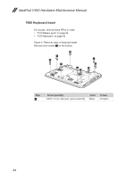
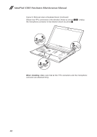
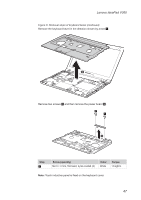
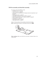
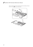
Lenovo IdeaPad V360 Figure 9. Removal steps of system board Remove two screws 1, and detach the LCD connector, speaker connectors and bluetooth connector in the direction shown by arrows 2. 1 2 1 2 2 2 When installing: Make sure that all the connectors are attached firmly. Step 1 Screw (quantity) M2.5 × 6 mm, flat-head, nylok-coated (2) Color White Torque 3.0 kgfcm When installing: Make sure that the LCD connector is attached firmly and make sure that you do not pinch the antenna cables when you attach the LCD assembly. 49
-
 1
1 -
2
-
3
-
4
-
5
-
6
-
7
-
8
-
9
-
10
-
11
-
12
-
13
-
14
-
15
-
16
-
17
-
18
-
19
-
20
-
21
-
22
-
23
-
24
-
25
-
26
-
27
-
28
-
29
-
30
-
31
-
32
-
33
-
34
-
35
-
36
-
37
-
38
-
39
-
40
-
41
-
42
-
43
-
44
-
45
-
46
-
47
-
 48
48 -
 49
49 -
 50
50 -
 51
51 -
 52
52 -
 53
53 -
 54
54 -
 55
55 -
 56
56 -
 57
57 -
 58
58 -
59
-
60
-
61
-
62
-
63
-
64
-
65
-
66
-
67
-
68
-
69
-
70
-
71
-
72
-
73
-
74
-
75
-
76
-
77
-
78
-
79
-
80
-
81
-
82
-
83
-
84
-
85
-
86
-
87
 |
 |

49
Lenovo IdeaPad V360
Figure 9. Removal steps of system board
Remove
two screws
1
, and
detach the LCD connector, speaker connectors
and bluetooth connector in the direction shown by arrows
2
.
1
2
2
2
2
1
When installing:
Make sure that
all the connectors are
attached firmly.
Step
Screw (quantity)
Color
Torque
1
M2.5 × 6 mm, flat-head, nylok-coated (2)
White
3.0 kgfcm
When installing:
Make sure that the LCD connector is attached firmly and
make sure that you do not pinch the antenna cables when you attach the LCD
assembly.