Lenovo PC 300PL Installing Options in your PC - 6862, 6275 - Page 57
Routing a Cable from an Adapter to a Drive in Bay 1
 |
View all Lenovo PC 300PL manuals
Add to My Manuals
Save this manual to your list of manuals |
Page 57 highlights
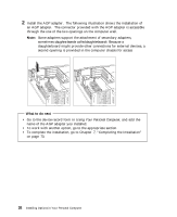
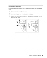
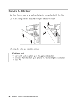
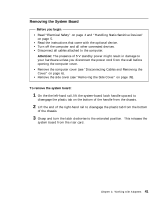
To install the system board: 1 Make sure the system-board latch handle is in the extended position. 2 Align the system-board rails with the tracks on the chassis. Grasp the rails and slide the board in until it is approximately 6 mm. (0.25 in.) from the riser card edge connector. 3 Rotate the latch handle counter-clockwise until the system board is properly aligned with the riser card edge connector. Continue rotating the latch handle counter clockwise while firmly pushing on the end of the right-hand rail. When the system board is fully seated the tab on the right-hand rail is engaged in an opening in the chassis. CAUTION: Do not push on the microprocessor, memory modules, memory sockets, or other system-board components to install the system board. 4 Push down on the latch handle to engage the tab on the under side into the opening in the chassis. This holds the latch in the latched position. System Board Push Here Hole Tab Tab Note: You cannot see the connection with a full-sized adapter in place. To make sure the system board is fully seated, it is important that the tab on the right-hand rail is engaged in the opening in the chassis. Routing a Cable from an Adapter to a Drive in Bay 1, 2, or 3 Use the following instructions to route a cable from a drive installed in bay 1, 2, or 3 to an adapter. To access the connector on the drives, rotate the drive cage using the instructions in "Rotating the Drive Cage" on page 54. Chapter 4. Working with Adapters 43
-
 1
1 -
2
-
3
-
4
-
5
-
6
-
7
-
8
-
9
-
10
-
11
-
12
-
13
-
14
-
15
-
16
-
17
-
18
-
19
-
20
-
21
-
22
-
23
-
24
-
25
-
26
-
27
-
28
-
29
-
30
-
31
-
32
-
33
-
34
-
35
-
36
-
37
-
38
-
39
-
40
-
41
-
42
-
43
-
44
-
45
-
46
-
47
-
48
-
49
-
50
-
51
-
 52
52 -
 53
53 -
 54
54 -
 55
55 -
 56
56 -
 57
57 -
 58
58 -
 59
59 -
 60
60 -
 61
61 -
 62
62 -
63
-
64
-
65
-
66
-
67
-
68
-
69
-
70
-
71
-
72
-
73
-
74
-
75
-
76
-
77
-
78
-
79
-
80
-
81
-
82
-
83
-
84
-
85
-
86
-
87
-
88
-
89
-
90
-
91
-
92
-
93
-
94
-
95
-
96
-
97
-
98
-
99
-
100
-
101
-
102
-
103
-
104
-
105
-
106
-
107
-
108
 |
 |
