Lenovo PC 300PL Installing Options in your PC300PL - 6592 - Page 67
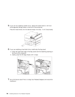
Use the tip of a screwdriver, if necessary, to flex the plastic tabs holding
 |
View all Lenovo PC 300PL manuals
Add to My Manuals
Save this manual to your list of manuals |
Page 67 highlights
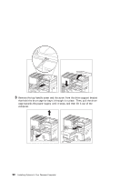
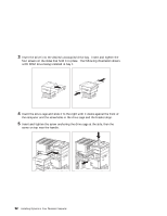
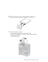
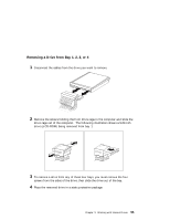
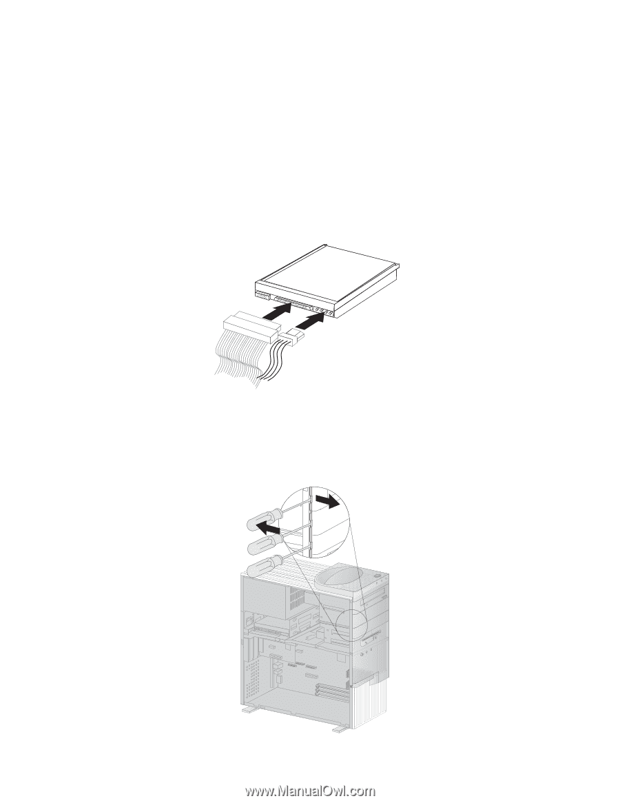
6 Attach the cables. Refer to "Power and Signal Cables" on page 47 for an illustration showing the locations of the connectors on the riser card. 7 Remove the bay panel, if necessary. a. Locate the appropriate bay panel in the computer cover. b. Use the tip of a screwdriver, if necessary, to flex the plastic tabs holding the bay panel in the cover. c. Remove the bay panel. Chapter 5. Working with Internal Drives 53 Socket 7
-
 1
1 -
2
-
3
-
4
-
5
-
6
-
7
-
8
-
9
-
10
-
11
-
12
-
13
-
14
-
15
-
16
-
17
-
18
-
19
-
20
-
21
-
22
-
23
-
24
-
25
-
26
-
27
-
28
-
29
-
30
-
31
-
32
-
33
-
34
-
35
-
36
-
37
-
38
-
39
-
40
-
41
-
42
-
43
-
44
-
45
-
46
-
47
-
48
-
49
-
50
-
51
-
52
-
53
-
54
-
55
-
56
-
57
-
58
-
59
-
60
-
61
-
 62
62 -
 63
63 -
 64
64 -
 65
65 -
 66
66 -
 67
67 -
 68
68 -
 69
69 -
 70
70 -
 71
71 -
 72
72 -
73
-
74
-
75
-
76
-
77
-
78
-
79
-
80
-
81
-
82
-
83
-
84
-
85
-
86
-
87
-
88
-
89
-
90
-
91
-
92
-
93
-
94
-
95
-
96
-
97
-
98
-
99
-
100
 |
 |
6
Attach the cables.
Refer to “Power and Signal Cables” on page
47 for an
illustration showing the locations of the connectors on the riser card.
7
Remove the bay panel, if necessary.
a.
Locate the appropriate bay panel in the computer cover.
b.
Use the tip of a screwdriver, if necessary, to flex the plastic tabs holding
the bay panel in the cover.
c.
Remove the bay panel.
Socket 7
Socket 7
Chapter
5.
Working with Internal Drives
53