Lenovo ThinkPad A20p TP A20 - User's Reference Supplement Guide html format - Page 4
Using the card stopper for the Mini-PCI Card
 |
View all Lenovo ThinkPad A20p manuals
Add to My Manuals
Save this manual to your list of manuals |
Page 4 highlights
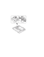
Using the card stopper for the Mini-PCI Card The Mini-PCI Card is held in place by a card stopper shown in the drawing below. Following is the overall procedure for replacing the Mini-PCI Card. For more detailed drawings with text, see the online user's guide. 1 Turn off the computer; then disconnect the ac adapter and all cables from the computer. 2 Remove the battery pack. 3 Loosen the screw on the Mini-PCI Card slot cover at the bottom of the computer; then remove the cover. 4 Release the card stopper by lifting it 1 . 5 Press out on the latches on both sides of the socket at the same time until the card moves up 2 . 6 Disconnect the cable from the card 3 ; then remove the card 4 . 7 Connect the cable to the new Mini-PCI Card. 8 Align the contact edge of the Mini-PCI Card with the corresponding socket of the computer, at an angle of about 45 degrees. Insert the Mini-PCI Card into the socket. 9 Pivot the card until it snaps into place. Make sure that the card is firmly fixed in the slot and does not move easily. 10 Fasten the card stopper by pressing it down. Make sure that both latches snap into place. Also make sure that the arrow mark Ɉ on the stopper points toward the card connector. 11 Align the tabs of the Mini-PCI Card slot cover with the corresponding slots; then press the cover flat. 12 Tighten the screw of the cover. 13 Put the battery pack back in place, and turn the computer on. 4
-
 1
1 -
 2
2 -
 3
3 -
 4
4 -
 5
5 -
 6
6 -
 7
7 -
 8
8 -
 9
9 -
 10
10 -
11
-
12
-
13
-
14
-
15
-
16
 |
 |
