Lenovo Y500 Hardware Maintenance Manual
Lenovo Y500 Manual
 |
View all Lenovo Y500 manuals
Add to My Manuals
Save this manual to your list of manuals |
Lenovo Y500 manual content summary:
- Lenovo Y500 | Hardware Maintenance Manual - Page 1
Lenovo Y400/Y500 Hardware Maintenance Manual - Lenovo Y500 | Hardware Maintenance Manual - Page 2
using this information and the product it supports, be sure to read the general information under "Notices" on page 97. First Edition (September 2012) © Copyright Lenovo 2012. All rights reserved. LENOVO products, data, computer software, and services have been developed exclusively at private - Lenovo Y500 | Hardware Maintenance Manual - Page 3
down the computer 26 Lenovo Y400/Y500 27 Specifications 27 Status indicators 30 Fn key combinations 32 FRU replacement notices 33 Screw notices 33 Removing and replacing an FRU 34 1010 Battery pack 35 1020 Dummy card 36 1030 Optical drive 37 1040 Hard disk drive(HDD)/Memory/ Mini PCI - Lenovo Y500 | Hardware Maintenance Manual - Page 4
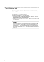
About this manual This manual contains service and reference information for the following Lenovo product: IdeaPad Y400/Y500 Use this manual to troubleshoot problems. The manual is divided into the following sections: • The common sections provide general information, guidelines, and safety - Lenovo Y500 | Hardware Maintenance Manual - Page 5
the following safety information that you need to get familiar with before you service a Lenovo computer: • see "General safety" on page 2 • see "Electrical safety" on page 3 • see "Safety inspection guide" on page 5 • see "Handling devices that are sensitive to electrostatic discharge" on page - Lenovo Y500 | Hardware Maintenance Manual - Page 6
Lenovo Y400/Y500 Hardware Maintenance Manual General safety Follow these rules below to ensure general conditions that may be hazardous to your eyes. • After service, reinstall all safety shields, guards, labels, and ground wires. Replace any safety device that is worn or defective. • Reinstall - Lenovo Y500 | Hardware Maintenance Manual - Page 7
you from grounds such as metal floor strips and machine frames. Observe the special safety precautions when you work with very high voltages; instructions for these precautions are in the safety sections of maintenance information. Be extremely careful when you measure the high voltages. • Regularly - Lenovo Y500 | Hardware Maintenance Manual - Page 8
Lenovo Y400/Y500 Hardware Maintenance Manual • Always look carefully for possible hazards in your The surface is conductive; such touching can cause personal injury and machine damage. • Do not service the following parts with the power on when they are removed from their normal operating places - Lenovo Y500 | Hardware Maintenance Manual - Page 9
safety items were installed to protect users and service personnel from injury. This guide addresses only those items. You should use or bulging batteries. 5. Remove the cover. 6. Check for any obvious non-Lenovo alterations. Use good judgment as to the safety of any non-Lenovo alterations. 7. - Lenovo Y500 | Hardware Maintenance Manual - Page 10
Lenovo Y400/Y500 Hardware Maintenance Manual Handling devices that are sensitive to electrostatic discharge even when you are wearing a wrist strap. • Use the black side of a grounded work mat to provide a static-free work surface. The mat is especially useful when handling ESD-sensitive devices - Lenovo Y500 | Hardware Maintenance Manual - Page 11
this section are provided in English, French, German, Hebrew, Italian, Japanese, and Spanish. Safety notice 1 Before the computer is powered on after FRU replacement, make sure all screws, springs, and other small parts are in place and are not left loose inside the computer. Verify this by shaking - Lenovo Y500 | Hardware Maintenance Manual - Page 12
Lenovo Y400/Y500 Hardware Maintenance Manual Safety notice 2 DANGER Some standby batteries contain a small amount of nickel and cadmium. Do not disassemble a standby battery, recharge it, throw it into fire or water, or short-circuit it. Dispose of the battery as required by local ordinances or - Lenovo Y500 | Hardware Maintenance Manual - Page 13
pack as required by local ordinances or regulations. Use only the battery in the appropriate parts listing when replacing the battery pack. Use of an incorrect battery can result in ignition or explosion of the battery. La batterie contient du nickel. Ne la démontez pas, ne l'exposez ni au feu - Lenovo Y500 | Hardware Maintenance Manual - Page 14
Lenovo Y400/Y500 Hardware Maintenance Manual Safety notice 4 DANGER The lithium battery can cause a fire, an explosion, or a severe burn. Do not recharge it, remove its polarized connector, disassemble it, heat it above 100°C (212°F), incinerate it, - Lenovo Y500 | Hardware Maintenance Manual - Page 15
Safety information Safety notice 5 If the LCD breaks and the fluid from inside the LCD gets into your eyes or on your hands, immediately wash the affected areas with water at least for 15 minutes. Seek medical care if any symptoms caused by the fluid are present after washing. Si le panneau d' - Lenovo Y500 | Hardware Maintenance Manual - Page 16
Lenovo Y400/Y500 Hardware Maintenance Manual Safety notice 6 DANGER To avoid shock, do not remove the plastic cover that protects the lower part of the inverter card. entzünden oder Verletzungen bei Personen hervorzurufen. Sebbene le batterie di alimentazione siano a basso voltaggio, una batteria in - Lenovo Y500 | Hardware Maintenance Manual - Page 17
Safety information Safety notice 8 DANGER Before removing any FRU, turn off the computer, unplug all power cords from electrical outlets, remove the battery pack, and then disconnect any interconnecting cables. Avant de retirer une unité remplaçable en clientèle, mettez le système hors tension, dé - Lenovo Y500 | Hardware Maintenance Manual - Page 18
Lenovo Y400/Y500 Hardware Maintenance Manual Laser compliance statement Some models of Lenovo computer are equipped from the factory with an optical storage device such as a CD-ROM drive or a DVD-ROM drive. Such devices are also sold separately as options. If one of these drives is installed, it is - Lenovo Y500 | Hardware Maintenance Manual - Page 19
Safety information A CD-ROM drive, a DVD-ROM drive, or any other storage device installed may contain an embedded Class 3A or Class 3B laser diode. Note the following: DANGER Emits visible and invisible - Lenovo Y500 | Hardware Maintenance Manual - Page 20
FRUs listed in this manual. After a system board is replaced, ensure that the latest BIOS is loaded to the system board before completing the service action. To download software fixes, drivers, and BIOS, follow the steps below: 1. Go to http://consumersupport.lenovo.com/. 2. Enter the serial number - Lenovo Y500 | Hardware Maintenance Manual - Page 21
(using the View Configuration option); then, when service has been completed, verify that those settings remain in effect. Strategy for replacing a hard disk drive Always try to run a low-level format before replacing a hard disk drive. This will cause all customer data on the hard disk to be lost - Lenovo Y500 | Hardware Maintenance Manual - Page 22
Lenovo Y400/Y500 Hardware Maintenance Manual Important information about replacing RoHS compliant FRUs support Lenovo's requirements and schedule in the EU. Products sold in 2005 and 2006 will contain some RoHS compliant FRUs. The following statement pertains to these products and any product Lenovo - Lenovo Y500 | Hardware Maintenance Manual - Page 23
Drives in the computer that you are servicing sequence might have been altered. If you select an incorrect drive, data or programs might be overwritten. • Replace , electrostatic discharge, or software errors. Consider replacing an FRU only when a problem recurs. If you suspect that an FRU is - Lenovo Y500 | Hardware Maintenance Manual - Page 24
keys caused by spilling a liquid onto the keyboard • Use of an incorrect AC adapter on laptop products The following symptoms might indicate damage caused by nonwarranted activities: • Missing parts might be a symptom of unauthorized service or modification. • If the spindle of a hard disk drive - Lenovo Y500 | Hardware Maintenance Manual - Page 25
differ from the one you are servicing. 3. If the voltage is not correct, replace the AC adapter. 4. If the voltage is acceptable, do the following: • Replace the system board. • If the problem persists, go to see "Lenovo Y400/Y500" on page 27. Note: Noise from the AC adapter does not always indicate - Lenovo Y500 | Hardware Maintenance Manual - Page 26
Lenovo Y400/Y500 Hardware Maintenance Manual Perform operational charging. If the battery status indicator or icon does not light on, remove the battery pack and let it return to room temperature. Reinstall the battery pack. If the charge indicator or icon is still off, replace the battery pack. If - Lenovo Y500 | Hardware Maintenance Manual - Page 27
Disc into the optical drive. 2. Start the computer. When the Lenovo logo comes up, immediately press F12; on the boot sequence menu, select the optical drive as the first boot-up device. The computer will boot from the Start Recovery Disc. Follow the on-screen instructions to begin the recovery - Lenovo Y500 | Hardware Maintenance Manual - Page 28
hard disk drive. The hard disk drive can be replaced for a scheduled fee. Supervisor password A supervisor password (SVP) protects the system information stored in the BIOS Setup Utility. The user must enter the SVP in order to get access to the BIOS Setup Utility and change the system configuration - Lenovo Y500 | Hardware Maintenance Manual - Page 29
monitor" timer in the operating system expires, the LCD backlight turns off. You can also turn off the LCD backlight by pressing Fn+F2. To end screen blank mode and resume normal operation, press any key following: • Close the display panel. • Press the hard disk is spinning can damage the hard - Lenovo Y500 | Hardware Maintenance Manual - Page 30
Lenovo Y400/Y500 Hardware Maintenance Manual Shutting down the computer If you are not going to use your computer for a long time, shut it down. To shut down your computer: 1. Open the charms, select Settings . 2. Select Power → Shut down. 26 - Lenovo Y500 | Hardware Maintenance Manual - Page 31
Y400/Y500 Lenovo Y400/Y500 This chapter presents the following product-specific service references and product-specific parts information: • see "Specifications" on page 27 • see "Status indicators" on page 30 • "FRU tests" on page 31 • see "Fn key combinations" on page 32 • see "FRU replacement - Lenovo Y500 | Hardware Maintenance Manual - Page 32
Feature Standard memory CMOS RAM Hard disk drive Solid-state drive Optical drive I/O port MODEM slot Audio Video Ethernet (on the system board) PCI Express Mini Card slot WLAN WWAN Bluetooth wireless Keyboard Touch pad Description • DDR3 1600 (Support Dual Channel)* • SODIMM × 2 • 256 bytes • 500GB - Lenovo Y500 | Hardware Maintenance Manual - Page 33
Lenovo Y400/Y500 Table 1. Specifications (continued) Feature Finger Print Reader Integrated camera Battery AC adapter Pre-installed operating system Description • N/A • HD Camera • 6 cells, 72WH/62WH • 120W/170W • Win8/Linpus 29 - Lenovo Y500 | Hardware Maintenance Manual - Page 34
Lenovo Y400/Y500 Hardware Maintenance Manual Status indicators The system status indicators below show the computer status: Y500 a b c d e 30 - Lenovo Y500 | Hardware Maintenance Manual - Page 35
the computer is operating on battery power with the remaining power between 20% and 80% of its capacity. White: The touchpad is disabled. d Caps lock e Num lock White: Caps Lock mode is enabled. You can enter all alphabetic characters (A-Z) in uppercase without pressing the Shift key. To enable or - Lenovo Y500 | Hardware Maintenance Manual - Page 36
F11: Fn + F12: Fn + PrtSc: Fn + Insert (Y500): Fn + PgUp (Y400): Fn + Home: Fn + End: Fn + PgDn (Y400): Fn Fn Fn + Space (on select models): Cancel hotkey. Enter sleep mode. Turn on/off the backlight of the LCD screen. Open the interface for selecting display options. Toggle airplane mode on/off - Lenovo Y500 | Hardware Maintenance Manual - Page 37
Lenovo Y400/Y500 FRU replacement notices This section presents notices related to removing and replacing parts. Read this section carefully before replacing any FRU. Screw notices Loose screws can cause a reliability problem. In the Lenovo computer, this problem is addressed with special nylon- - Lenovo Y500 | Hardware Maintenance Manual - Page 38
Lenovo Y400/Y500 Hardware Maintenance Manual Removing and replacing an FRU This section presents exploded figures with the instructions to indicate how to remove and replace the FRU. Make sure to observe the following general rules: 1. Do not attempt to service any computer unless you have been - Lenovo Y500 | Hardware Maintenance Manual - Page 39
Lenovo Y400/Y500 1010 Battery pack DANGER Only use the battery specified in the parts list for your computer. Any other battery could ignite or explode. Figure 1. Removal steps of battery pack Unlock the manual battery latch a. Holding the spring-loaded battery latch in the unlocked position b, - Lenovo Y500 | Hardware Maintenance Manual - Page 40
Lenovo Y400/Y500 Hardware Maintenance Manual 1020 Dummy card For access, remove this FRU: • see "1010 Battery pack" on page 35 Figure 2. Removal steps of dummy cards Remove the dummy card in the direction shown by arrows a b . a b 36 - Lenovo Y500 | Hardware Maintenance Manual - Page 41
Lenovo Y400/Y500 1030 Optical drive For access, remove this FRU: • see "1010 Battery pack" on page 35 Figure 3. Removal steps of optical drive Push the latch in the direction shown by arrow a. Hold the spring-loaded latch in the unlocked position b. Gently pull out the optional module in - Lenovo Y500 | Hardware Maintenance Manual - Page 42
Lenovo Y400/Y500 Hardware Maintenance Manual 1040 Hard disk drive(HDD)/Memory/Mini PCI Express Card slot compartment cover For access, remove these FRUs in order: • see "1010 Battery pack" on page 35 • see "1030 Optical drive" on page 37 Figure 4. Removal steps of HDD/Memory/Mini PCI Express Card - Lenovo Y500 | Hardware Maintenance Manual - Page 43
Lenovo Y400/Y500 1050 Hard disk drive For access, remove these FRUs in order: • see "1010 Battery pack" on page 35 • see "1040 Hard disk drive(HDD)/Memory/Mini PCI Express Card slot compartment cover" on page 38 Attention: • Do not drop the hard disk drive or apply any physical shock to it. The hard - Lenovo Y500 | Hardware Maintenance Manual - Page 44
Lenovo Y400/Y500 Hardware Maintenance Manual Figure 5. Removal steps of hard disk drive (continued) Pull the tab in the direction shown by arrow b . b Take out the hard disk drive secured in a metal frame c . c When installing: Make sure that the HDD connector is attached firmly. 40 - Lenovo Y500 | Hardware Maintenance Manual - Page 45
Lenovo Y400/Y500 1060 DIMM For access, remove these FRUs in order: • see "1010 Battery pack" on page 35 • see "1040 Hard disk drive(HDD)/Memory/Mini PCI Express Card b Note: If only one DIMM is used on the computer you are servicing, the card must be installed in SLOT-0 ( : lower slot), but not in - Lenovo Y500 | Hardware Maintenance Manual - Page 46
Lenovo Y400/Y500 Hardware Maintenance Manual 1070 PCI Express Mini Card for wireless LAN/WAN For access, remove these FRUs in order: • see "1010 Battery pack" on page 35 • see "1040 Hard disk drive(HDD)/Memory/Mini PCI Express Card slot compartment cover" on page 38 Figure 7. Removal steps of PCI - Lenovo Y500 | Hardware Maintenance Manual - Page 47
Lenovo Y400/Y500 Figure 7. Removal steps of PCI Express Mini Card for wireless LAN/WAN (continued) When installing: • In models with a wireless LAN card that has two antenna connectors, plug the black cable (1st) (MAIN) into the jack labeled 1, and the white cable (2nd) (AUX) into jack labeled 2 on - Lenovo Y500 | Hardware Maintenance Manual - Page 48
Lenovo Y400/Y500 Hardware Maintenance Manual 1080 Keyboard For access, remove these FRUs in order: • see "1010 Battery pack" on page 35 • see "1030 Optical drive" on page 37 • see "1040 Hard disk drive(HDD)/Memory/Mini PCI Express Card slot compartment cover" on page 38 • see "1050 Hard disk drive" - Lenovo Y500 | Hardware Maintenance Manual - Page 49
Lenovo Y400/Y500 Figure 8. Removal steps of keyboard (continued) Push the back of the keyboard in the direction shown by arrow a. Loosen the keyboard with fingers in the direction shown by arrow b. Lift the keyboard a little c, and then detach the connectors in the direction shown by arrows d e. a - Lenovo Y500 | Hardware Maintenance Manual - Page 50
Lenovo Y400/Y500 Hardware Maintenance Manual Figure 8. Removal steps of keyboard (continued) c Y500 e d 46 - Lenovo Y500 | Hardware Maintenance Manual - Page 51
Lenovo Y400/Y500 1090 Keyboard bezel For access, remove these FRUs in order: • see "1010 Battery pack" on page 35 • see "1020 Dummy card" on page 36 • see "1030 Optical drive" on page 37 • see "1040 Hard disk drive(HDD)/Memory/Mini PCI Express Card slot compartment cover" on page 38 • see "1050 - Lenovo Y500 | Hardware Maintenance Manual - Page 52
Lenovo Y400/Y500 Hardware Maintenance Manual Figure 9. Removal steps of keyboard bezel (continued) Y500: Remove four screws a , three screws b on the bottom. b bb a a aa Step a Screw (quantity) Color M2.5 × 10 mm, flat-head, nylok-coated(4) Black M2 × 3 mm, flat-head, nylok-coated (3) - Lenovo Y500 | Hardware Maintenance Manual - Page 53
Lenovo Y400/Y500 Figure 9. Removal steps of keyboard bezel (continued) Y500: Remove the screw c . Detach the power board connector and TouchPad cable in the direction shown by arrows d e . IO board connector in the direction shown by arrow f . d Y500 c e f Step a Screw (quantity) Color M2.5 - Lenovo Y500 | Hardware Maintenance Manual - Page 54
Lenovo Y400/Y500 Hardware Maintenance Manual Figure 9. Removal steps of keyboard bezel (continued) Remove the keyboard bezel in the direction shown by arrow g. Y500 g 50 - Lenovo Y500 | Hardware Maintenance Manual - Page 55
an ESD mat or conductive corrugated material. For access, remove these FRUs in order: • see "1010 Battery pack" on page 35 • see "1020 Dummy card" on page 36 • see "1030 Optical drive" on page 37 • see "1040 Hard disk drive(HDD)/Memory/Mini PCI Express Card slot compartment cover" on page 38 • see - Lenovo Y500 | Hardware Maintenance Manual - Page 56
Lenovo Y400/Y500 Hardware Maintenance Manual Figure 10. Removal steps of system board Y400: Remove screws a . Detach camera connector in the direction shown by arrow b , unplug DC-IN connector in the direction shown by arrow c , LCD connector in the direction shown by arrow d . a - Lenovo Y500 | Hardware Maintenance Manual - Page 57
Lenovo Y400/Y500 Figure 10. Removal steps of system board Y500: Loosen three screws a . Unplug LCD, speakers cable connector, DC-IN, camera connectors in the direction shown by arrows b . a a Y500 b b b 53 - Lenovo Y500 | Hardware Maintenance Manual - Page 58
Lenovo Y400/Y500 Hardware Maintenance Manual Figure 10. Removal steps of system board a b When installing: Make sure that all the connectors are attached firmly. Step Screw (quantity) a M2.5 × 4 mm, flat-head, nylok-coated (3) Color Torque Black 1.5 ~2.0 kgfcm Remove the system board in the - Lenovo Y500 | Hardware Maintenance Manual - Page 59
Lenovo Y400/Y500 1110 LCD unit For access, remove these FRUs in order: • see "1010 Battery pack" on page 35 • see "1020 Dummy card" on page 36 • see "1030 Optical drive" on page 37 • see "1040 Hard disk drive(HDD)/Memory/Mini PCI Express Card slot compartment cover" on page 38 • see "1050 Hard disk - Lenovo Y500 | Hardware Maintenance Manual - Page 60
Lenovo Y400/Y500 Hardware Maintenance Manual Figure 11. Removal steps of LCD unit (continued) Y500: Release the antenna cables from the cable guides in the direction shown by arrows a. Remove four screws b. bb Y500 a a bb a Step b Screw (quantity) M2.5 × 5 mm, flat-head, nylok-coated (4) Color - Lenovo Y500 | Hardware Maintenance Manual - Page 61
Lenovo Y400/Y500 Figure 11. Removal steps of LCD unit (continued) Remove the LCD unit in the direction shown by arrows c. Y500 c c 57 - Lenovo Y500 | Hardware Maintenance Manual - Page 62
Lenovo Y400/Y500 Hardware Maintenance Manual 1120 Fan assembly and Heat Sink assembly For access, remove these FRUs in order: • see "1010 Battery pack" on page 35 • see "1020 Dummy card" on page 36 • see "1030 Optical drive" on page 37 • see "1040 Hard disk drive(HDD)/Memory/Mini PCI Express Card - Lenovo Y500 | Hardware Maintenance Manual - Page 63
Lenovo Y400/Y500 Figure 12. Removal steps of fan assembly and heat sink assembly Detach the fan connector in the direction shown by arrow a and loosen six screws b - Lenovo Y500 | Hardware Maintenance Manual - Page 64
Lenovo Y400/Y500 Hardware Maintenance Manual 1130 CPU For access, remove these FRUs in order: • see "1010 Battery pack" on page 35 • see "1020 Dummy card" on page 36 • see "1030 Optical drive" on page 37 • see "1040 Hard disk drive(HDD)/Memory/Mini PCI Express Card slot compartment cover" on page 38 - Lenovo Y500 | Hardware Maintenance Manual - Page 65
Lenovo Y400/Y500 1140 Base cover, speakers and power assembly For access, remove these FRUs in order: • see "1010 Battery pack" on page 35 • see "1020 Dummy card" on page 36 • see "1030 Optical drive" on page 37 • see "1040 Hard disk drive(HDD)/Memory/Mini PCI Express Card slot compartment cover" on - Lenovo Y500 | Hardware Maintenance Manual - Page 66
Lenovo Y400/Y500 Hardware Maintenance Manual Figure 14. Removal steps of base cover, speakers and power assembly (continued) Y500: a a Y500 b a a b Step Screw (quantity) a M2.0 × 3 flat-head, nylok-coated (4) Color Black Torque 1.0 ~ 1.5 kgfcm 62 - Lenovo Y500 | Hardware Maintenance Manual - Page 67
Lenovo Y400/Y500 Figure 14. Removal steps of base cover, speakers and power assembly (continued) Y400: Loosen the screws a, installing: Make sure that the power connector is attached firmly. Step Screw (quantity) a M2.0 × 3 mm, flat-head, nylok-coated (2) Color Black Torque 1.0 ~ 1.5 kgfcm 63 - Lenovo Y500 | Hardware Maintenance Manual - Page 68
Y400/Y500 Hardware Maintenance Manual Figure 14. Removal steps of base cover, speakers and power assembly (continued) Y500: Loosen the screw a, then remove the power assembly in the direction shown by arrow b. a b Y500 Step Screw (quantity) a M2.0 × 3 mm, flat-head, nylok-coated (1) Color Black - Lenovo Y500 | Hardware Maintenance Manual - Page 69
Lenovo Y400/Y500 Note: Applying labels to the base cover The new base cover FRU is shipped with a kit containing labels of several kinds. When you replace the base WLAN Label or SIRIM BT Label or ISRAEL WLAN label PRC/MTM CODE User guide label For some models, you also need to apply one or two FCC - Lenovo Y500 | Hardware Maintenance Manual - Page 70
Lenovo Y400/Y500 Hardware Maintenance Manual 1150 LCD front bezel For access, remove these FRUs in order: • see "1010 Battery pack" on page 35 • see "1020 Dummy card" on page 36 • see "1030 Optical drive" on page 37 • see "1040 Hard disk drive(HDD)/Memory/Mini PCI Express Card slot compartment cover - Lenovo Y500 | Hardware Maintenance Manual - Page 71
Lenovo Y400/Y500 Figure 15. Removal steps of LCD front bezel (continued) Remove the LCD front bezel in the direction shown by arrows a. a a a a 67 - Lenovo Y500 | Hardware Maintenance Manual - Page 72
Lenovo Y400/Y500 Hardware Maintenance Manual 1160 LCD panel, LCD cable and hinges For access, remove these FRUs in order: • see "1010 Battery pack" on page 35 • see "1020 Dummy card" on page 36 • see "1030 Optical drive" on page 37 • see "1040 Hard disk drive(HDD)/Memory/Mini PCI Express Card slot - Lenovo Y500 | Hardware Maintenance Manual - Page 73
Lenovo Y400/Y500 Figure 16. Removal steps of LCD panel, LCD cable and hinges (continued) Y500: Remove two screws a, six (Y400) M2.5 × 4, flat-head, nylok-coated (2) (Y500) M2.5 × 5 mm, flat-head, nylok-coated (6) (Y500) Color Black Silver Black Silver Torque 1.5 ~ 2.0 kgfcm 2.0 ~ 2.5 kgfcm 2.0 ~ - Lenovo Y500 | Hardware Maintenance Manual - Page 74
/Y500 Hardware Maintenance Manual Figure 16. Removal steps of LCD panel, LCD cable and hinges (continued) Y400: Remove four screws d, four screws e and the hinges in the direction shown by arrows f. dd ee f dd ee f Step a Screw (quantity) Color M2.0 × 3 mm, flat-head, nylok-coated (4) Black - Lenovo Y500 | Hardware Maintenance Manual - Page 75
Lenovo Y400/Y500 Figure 16. Removal steps of LCD panel, LCD cable and hinges (continued) Y500: Remove six screws d . Lift the LCD panel with hinges in the direction shown by arrows e . d d d d d d e e Step a Screw (quantity) Color M2.0 × 3 mm, flat-head, nylok-coated (6) Black Torque 1.0 ~ 1.5 - Lenovo Y500 | Hardware Maintenance Manual - Page 76
Lenovo Y400/Y500 Hardware Maintenance Manual 1170 Integrated camera For access, remove these FRUs in order: • see "1010 Battery pack" on page 35 • see "1020 Dummy card" on page 36 • see "1030 Optical drive" on page 37 • see "1040 Hard disk drive(HDD)/Memory/Mini PCI Express Card slot compartment - Lenovo Y500 | Hardware Maintenance Manual - Page 77
Lenovo Y400/Y500 Locations Front view a Integrated camera b Built-in microphone (with noise reduction) c Computer display d Power button e JBL speakers f Touchpad g Numeric keypad (Y500) h System status indicators i Memory card slot ba b c d Y500 e f hi g 73 - Lenovo Y500 | Hardware Maintenance Manual - Page 78
Lenovo Y400/Y500 Hardware Maintenance Manual Right-side view a Kensington slot b Optical drive c USB port d Microphone jack e Headphone jack Y400: Y500: a b c c d e a b c d e 74 - Lenovo Y500 | Hardware Maintenance Manual - Page 79
Bottom and Left-side view a Novo button b AC power adapter jack c Ventilation slots d VGA port e RJ-45 port f HDMI port g USB port h Battery latch - manual i Removable module lock j Battery pack k Battery latch - spring loaded l Louvers h l Lenovo Y400/Y500 ij k a b c d e f g g 75 - Lenovo Y500 | Hardware Maintenance Manual - Page 80
Lenovo Y400/Y500 Hardware Maintenance Manual Parts list This section presents the following service parts: • see "Overall" on page 77 • see "LCD FRUs" on page 83 • see "Keyboard" on page 86 • see "Miscellaneous parts" on page 92 • see "AC adapters" on page 93 • see "Power cords" on page 94 Notes: • - Lenovo Y500 | Hardware Maintenance Manual - Page 81
Overall Lenovo Y400/Y500 1 Y500 2 Y400 2 Y500 3 i c b Y400 f 4 6 i b Y500 7 d Y400 8 9 Y500 10 e 11 13 14 h Y400 15 17 16 18 19 14 f 22 Y500 20 24 25 21 26 23 32 27 35 28 34 36 30 29 g 31 38 40 a 33 37 39 77 - Lenovo Y500 | Hardware Maintenance Manual - Page 82
Lenovo Y400/Y500 Hardware Maintenance Manual Table 5. Parts list-Overall No. FRU FRU no. CRU ID 1 LCD unit (see "LCD FRUs" on page 83) 2 Keyboard (see "Keyboard" on page 86) 3 QIQY5 Function Board 3 QIQY6 Function Board W/Cable 4 QIQY5 Power Board 4 QIQY6 Power Board W/Cable 6 QIQY5 Upper Case 6 - Lenovo Y500 | Hardware Maintenance Manual - Page 83
, Ivy bridge core Quad-Core 35W Intel 102500437 N I7-3632QM 2.2G E1 6M 4cPGA CPU 8 Processor, Ivy bridge core Dual Core 35W Intel 102500295 N I7-3520M 2.9G L1 4M 2cPGA processor 8 Processor, Ivy bridge core Dual Core 35W Intel 102500297 N I5-3360M 2.8G L1 3M 2cPGA processor 8 Processor, Ivy - Lenovo Y500 | Hardware Maintenance Manual - Page 84
Lenovo Y400/Y500 Hardware Maintenance Manual 20200224 ** 13 QIQY5 Audio Board 90001124 N 13 QIQY6 USB Board W/Cable 90001163 N Card 90201944 * 18 QIQY6 SD Dummy Card 90201944 * 19 SSD, mSATA 16G Samsung MZMPA016HMCD 16G 16200255 ** mSATA SSD 19 SSD, mSATA 16G Sandisk U100 16G mSATA - Lenovo Y500 | Hardware Maintenance Manual - Page 85
Lenovo Y400/Y500 * DVD Rambo ODD 34 ODD, 9.5mm Tray in Rambo PSN UJ8B2 Slim Tray 25204157 * DVD Rambo Card 90201939 * 36 QIQY6 ODD Dummy Card 90201981 * 37 QIQY5 VGA Thermal Pad 90201965 N 38 Hard disk drive, 500G 5400rpm ST500LM012 5.4K 9.5 16200210 ** 500G HDD 38 Hard disk drive - Lenovo Y500 | Hardware Maintenance Manual - Page 86
Lenovo Y400/Y500 Hardware Maintenance Manual Table 5. Parts list-Overall (continued) No. FRU 39 QIQY5 Thermal Door 39 QIQY6 Thermal Door 40 QIQY5 2ND VGA Board 40 QIQY6 2ND VGA Board FRU no. CRU ID 90201951 ** 90201985 ** 90001120 * 90001120 * 82 - Lenovo Y500 | Hardware Maintenance Manual - Page 87
Lenovo Y400/Y500 LCD FRUs In Lenovo Y400/Y500, there are following types of LCDs. • "14.0-in. HD TFT" Y400 • "15.6-in. HD TFT" Y500 1 2 4 6 11 9 12 3 2 5 8 7 10 83 - Lenovo Y500 | Hardware Maintenance Manual - Page 88
Lenovo Y400/Y500 Hardware Maintenance Manual 14.0-in. HD TFT (Y400) Table 6. Parts list-14.0-in. HD TFT (HF) HD USB3 20200193 N NB camera 8 Camera, USB3.0 CCY CNFB1C021003350LH HD USB3 20200194 N NB camera 8 Camera, USB3.0 LTN 11P2SF170 HD USB3 NB camera 20200203 N 9 QIQY5 LCD Cover Sponge - Lenovo Y500 | Hardware Maintenance Manual - Page 89
Lenovo Y400/Y500 15.6-in. HD TFT (Y500) Table 6. Parts list-15.6-in. HD TFT No. FRU FRU no. CRU ID 6 Hinge Antenna 2.3/2.7GHz Chengjun Acon Chengjun 20200332 N Y500 2.4/2.5 Hinge ANT L 6 Hinge Antenna 2.3/2.7GHz Sinher Acon Sinher Y500 20200334 N 2.4/2.5 Hinge ANT L 6 Hinge Antenna 2.4/2. - Lenovo Y500 | Hardware Maintenance Manual - Page 90
Lenovo Y400/Y500 Hardware Maintenance Manual Keyboard Table 8. Parts list-Keyboard Language P/N CRU ID Y400 (Win 8) Chicony Chicony (Backlight) English U.K. English Italian Spanish Turkish Thai Portuguese Latin Canadian English&French Korean Traditional Chinese Russian French German Arabic - Lenovo Y500 | Hardware Maintenance Manual - Page 91
Lenovo Y400/Y500 Table 8. Parts list-Keyboard Language Y400 (Win 8) Chicony (Backlight) (continued) Sunrex Greek Hebrew Hungarian Four Nordic countries Belgian Icelandic Slovenian Swiss International English Czechoslovakian Bulgarian Indian English U.K. English Italian Spanish Turkish Thai - Lenovo Y500 | Hardware Maintenance Manual - Page 92
Lenovo Y400/Y500 Hardware Maintenance Manual Table 8. Parts list-Keyboard Language Y400 (Win 8) Sunrex (Backlight) Darfon English U.S. English U.K. English Italian Spanish Turkish Thai Portuguese Latin Canadian English&French Korean Traditional Chinese Russian French German Arabic Brazilian - Lenovo Y500 | Hardware Maintenance Manual - Page 93
Lenovo Y400/Y500 Table 8. Parts list-Keyboard Language Y400 (Win 8) Darfon (continued) Darfon (Backlight) Greek Hebrew Hungarian Four Nordic countries Belgian Icelandic Slovenian Swiss International English Czechoslovakian Bulgarian Indian English U.K. English U.S. English Italian Spanish - Lenovo Y500 | Hardware Maintenance Manual - Page 94
Lenovo Y400/Y500 Hardware Maintenance Manual Table 8. Parts list-Keyboard Language Y500 (Win 8) Chicony (Backlight) OKI (Backlight) English U.S. English U.K. English Italian Spanish Turkish Thai Portuguese Latin Canadian English&French Korean Traditional Chinese Russian French German Arabic - Lenovo Y500 | Hardware Maintenance Manual - Page 95
Lenovo Y400/Y500 Table 8. Parts list-Keyboard Language Y500 (Win 8) OKI (Backlight) (continued) Dafon (Backlight) Greek Hebrew Hungarian Four Nordic countries Belgian Icelandic Slovenian Swiss International English Czechoslovakian Bulgarian Indian English U.S. English U.K. English Italian - Lenovo Y500 | Hardware Maintenance Manual - Page 96
Lenovo Y400/Y500 Hardware Maintenance Manual Miscellaneous parts Table 9. Parts list-Miscellaneous parts FRU P/N CRU ID System miscellaneous parts: N • 90201945 90201941 90201995 90201960 Cable miscellaneous parts: N • (h) QIQY5 Audio Cable • (i) QIQY5 TP Cable • (i) QIQY6 TP Cable Note - Lenovo Y500 | Hardware Maintenance Manual - Page 97
Lenovo Y400/Y500 AC adapters Table 10. Parts list-3-pin AC adapters FRU 90W, Delta ADP-90DD BD 20V4.5A adapter 90W, Delta ADP-90DD BD 20V4.5A adapter-CCC 90W, Liteon PA-1900-56LC 20V4.5A adapter (330PF) 90W, Liteon PA-1900-56LC 20V4.5A adapter-CCC 90W, Chicony CPA-A090 20V4.5A adapter (330PF) 90W, - Lenovo Y500 | Hardware Maintenance Manual - Page 98
Lenovo Y400/Y500 Hardware Maintenance Manual Power cords A Lenovo power cord for a specific country or region is usually available only in that country or region: Table 11. Parts list-3-pin power cords Region China • - Lenovo Y500 | Hardware Maintenance Manual - Page 99
Lenovo Y400/Y500 Table 11. Parts list-3-pin power cords (continued) Region Brazil • Longwell LP-46+H03VV-F+LS-18 1m Israel • Longwell LP-41+H03VV-F+LS-18 1m - Lenovo Y500 | Hardware Maintenance Manual - Page 100
Lenovo Y400/Y500 Hardware Maintenance Manual Table 11. Parts list-3-pin power cords (continued) Region Argentina • VOLEX VA2073+H03VV-F+VAC5S 1m Brazil • VOLEX CH10S3+H03VV-F+VAC5S 1m Israel • VOLEX SI16S3+H03VV-F+ - Lenovo Y500 | Hardware Maintenance Manual - Page 101
and verify the operation of any other product, program, or service. Lenovo may have patents or pending patent applications covering subject matter described document are not intended for use in implantation or other life support applications where malfunction may result in injury or death to - Lenovo Y500 | Hardware Maintenance Manual - Page 102
and/or other countries: Lenovo® Lenovo logo® IdeaPad® VeriFace® OneKey Rescue® (OneKey Recovery, OneKey Antivirus) APS® Power Express® Energy Management and ReadyComm® The following terms are trademarks of Microsoft Corporation in the United States, other countries, or both: Windows® Windows® 7 The - Lenovo Y500 | Hardware Maintenance Manual - Page 103
Notices 99
-
 1
1 -
 2
2 -
 3
3 -
 4
4 -
 5
5 -
 6
6 -
 7
7 -
8
-
9
-
10
-
11
-
12
-
13
-
14
-
15
-
16
-
17
-
18
-
19
-
20
-
21
-
22
-
23
-
24
-
25
-
26
-
27
-
28
-
29
-
30
-
31
-
32
-
33
-
34
-
35
-
36
-
37
-
38
-
39
-
40
-
41
-
42
-
43
-
44
-
45
-
46
-
47
-
48
-
49
-
50
-
51
-
52
-
53
-
54
-
55
-
56
-
57
-
58
-
59
-
60
-
61
-
62
-
63
-
64
-
65
-
66
-
67
-
68
-
69
-
70
-
71
-
72
-
73
-
74
-
75
-
76
-
77
-
78
-
79
-
80
-
81
-
82
-
83
-
84
-
85
-
86
-
87
-
88
-
89
-
90
-
91
-
92
-
93
-
94
-
95
-
96
-
97
-
98
-
99
-
100
-
101
-
102
-
103
 |
 |
Lenovo Y400/Y500
Hardware
Maintenance
Manual