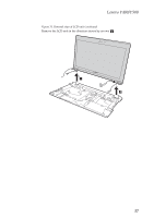
Lenovo Y500 Hardware Maintenance Manual - Page 63
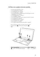
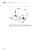
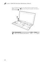
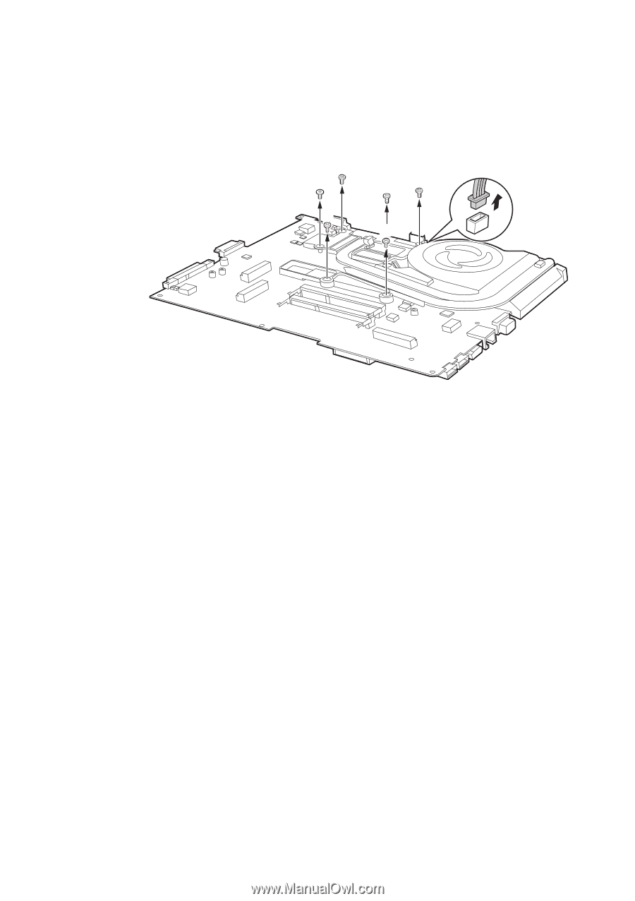
Removal steps of fan assembly and heat sink assembly
 |
View all Lenovo Y500 manuals
Add to My Manuals
Save this manual to your list of manuals |
Page 63 highlights
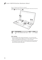
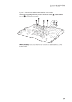
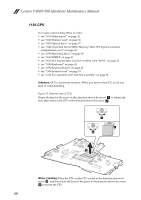
Lenovo Y400/Y500 Figure 12. Removal steps of fan assembly and heat sink assembly Detach the fan connector in the direction shown by arrow a and loosen six screws b to lift the fan assembly. b b bb b a b When installing: Make sure that the fan connector is attached firmly to the system board. 59
-
 1
1 -
2
-
3
-
4
-
5
-
6
-
7
-
8
-
9
-
10
-
11
-
12
-
13
-
14
-
15
-
16
-
17
-
18
-
19
-
20
-
21
-
22
-
23
-
24
-
25
-
26
-
27
-
28
-
29
-
30
-
31
-
32
-
33
-
34
-
35
-
36
-
37
-
38
-
39
-
40
-
41
-
42
-
43
-
44
-
45
-
46
-
47
-
48
-
49
-
50
-
51
-
52
-
53
-
54
-
55
-
56
-
57
-
 58
58 -
 59
59 -
 60
60 -
 61
61 -
 62
62 -
 63
63 -
 64
64 -
 65
65 -
 66
66 -
 67
67 -
 68
68 -
69
-
70
-
71
-
72
-
73
-
74
-
75
-
76
-
77
-
78
-
79
-
80
-
81
-
82
-
83
-
84
-
85
-
86
-
87
-
88
-
89
-
90
-
91
-
92
-
93
-
94
-
95
-
96
-
97
-
98
-
99
-
100
-
101
-
102
-
103
 |
 |
Lenovo Y400/Y500
59
Figure 12. Removal steps of fan assembly and heat sink assembly
Detach the fan connector in the direction shown by arrow
and loosen six
screws
to lift the fan assembly.
When installing:
Make sure that the fan connector is attached firmly to the
system board.
a
b
a
b
b
b
b
b
b