LiftMaster GH GH LOGIC VERSION 1 Manual
LiftMaster GH Manual
 |
View all LiftMaster GH manuals
Add to My Manuals
Save this manual to your list of manuals |
LiftMaster GH manual content summary:
- LiftMaster GH | GH LOGIC VERSION 1 Manual - Page 1
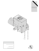
OWNER'S MANUAL GH SOLID STATE INDUSTRIAL DUTY DOOR OPERATOR LOGIC LCONTROL FACTORY SET C2 Wiring See pages 13 & 14 for other wiring configurations 2 YEAR WARRANTY Serial # (located on electrical box cover) Installation Date Wiring Type NOT FOR RESIDENTIAL USE 41B6 LISTED DOOR OPERATOR - LiftMaster GH | GH LOGIC VERSION 1 Manual - Page 2
43 R.P.M. DOOR SPEED 4 - 10" per sec. depending on door BRAKE Solenoid actuated disc brake HOIST WHEEL Standard mounting on left or right side SAFETY DISCONNECT Floor level chain hoist with electrical interlock for emergency manual door operation CLUTCH: (optional)....Adjustable torque limiter - LiftMaster GH | GH LOGIC VERSION 1 Manual - Page 3
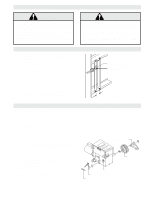
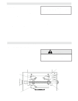
TENSION AND CAN CAUSE SERIOUS PERSONAL INJURY. CALL A PROFESSIONAL DOOR SERVICEMAN TO MOVE OR ADJUST DOOR SPRINGS OR HARDWARE. SITE PREPARATIONS It is imperative that the wall or mounting surface provide adequate support for the operator. This surface must: a) Be rigid to prevent play between - LiftMaster GH | GH LOGIC VERSION 1 Manual - Page 4
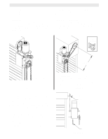
on page 3. Refer to the illustration and instructions below that suits your application. 1a. Wall Mounting The operator should generally be installed below the door shaft, and as close to the door as possible. The optimum distance between the door shaft and operator drive shaft is between 12" - 15 - LiftMaster GH | GH LOGIC VERSION 1 Manual - Page 5
it through both openings in the chain guide. Remove enough MANUAL OPERATION This operator has provisions for manually operating the door in case of emergency or power failure. Refer to the appropriate instructions below for your model operator. Model GH These operators are equipped with a manual - LiftMaster GH | GH LOGIC VERSION 1 Manual - Page 6
of door opening. 4. Repeat Steps 1 and 2 for close cycle. Adjust close limit nut so that actuator is engaged as door fully seats at the floor. WARNING TO AVOID SERIOUS PERSONAL INJURY OR DEATH FROM ELECTROCUTION, DISCONNECT ELECTRIC POWER BEFORE MANUALLY MOVING LIMIT NUTS. If other problems persist - LiftMaster GH | GH LOGIC VERSION 1 Manual - Page 7
OPEN" POSITION. IF THE DOOR LOCK NEEDS TO REMAIN FUNCTIONAL, INSTALL AN INTERLOCK SWITCH. 1-1/16" dia. Power Wiring Access Hole WARNING DISCONNECT POWER AT THE FUSE BOX BEFORE PROCEEDING. OPERATOR MUST BE PROPERLY GROUNDED AND CONNECTED IN ACCORDANCE WITH LOCAL ELECTRICAL CODES. NOTE: THE OPERATOR - LiftMaster GH | GH LOGIC VERSION 1 Manual - Page 8
. s Do not lubricate motor. Motor bearings are rated for continuous operation. s Inspect and service whenever a malfunction is observed or suspected. s CAUTION: BEFORE SERVICING, ALWAYS DISCONNECT OPERATOR FROM POWER SUPPLY. HOW TO ORDER REPAIR PARTS OUR LARGE SERVICE ORGANIZATION SPANS AMERICA - LiftMaster GH | GH LOGIC VERSION 1 Manual - Page 9
NEMA MOTOR WIRING DIAGRAMS SINGLE VOLTA G E 1/3 & 1/2HP 115V ONLY Motor Purple 115V T1-Blue Grey Blue T4-Yellow T5-Black Yellow Cable T8-Red 230V BRAKE SOLENOID (WHEN REQUIRED) Motor Grey BLACK/BLUE 115V T2-White T4-Yellow Blue T5-Black Purple Yellow Cable T3-Orange T1-Blue T8-Red BLACK - LiftMaster GH | GH LOGIC VERSION 1 Manual - Page 10
pressure to close. Release of close button will cause door to reverse (roll-back feature) plus wiring for sensing device to reverse. T* 3 Button, 1 Button, 1 & 3 Button Radio Control Function: Momentary contact to open, close, and stop, with open override and timer to close. Every device that - LiftMaster GH | GH LOGIC VERSION 1 Manual - Page 11
H L3 Neutral 115V, 208-230V, 1Ø Hot 115V, 208-230V, 1Ø TB112 3 4 5 6 7 8 9 10 12 3 Remove Jumper to Install Interlock Open / Close Open Close Stop RADIO CONTROL (24V dc only) Sensing Device GND STANDARD POWER & CONTROL CONNECTION DIAGRAM Solid State Board CDO - 208-230V3Ph L1 N 208-230V - LiftMaster GH | GH LOGIC VERSION 1 Manual - Page 12
12 - LiftMaster GH | GH LOGIC VERSION 1 Manual - Page 13
13 - LiftMaster GH | GH LOGIC VERSION 1 Manual - Page 14
mode (B2, C2, D1, E2, T, TS). Set max. run timer 1234 OFF Adjustable Mid Stop Set: Begin with door in closed position. Set dip switch to adj. mid stop mode. Press control station open button to operate door from closed to mid stop position and stop with control station stop button. Set dip switch - LiftMaster GH | GH LOGIC VERSION 1 Manual - Page 15
of door opening. 4. Repeat Steps 1 and 2 for close cycle. Adjust close limit nut so that actuator is engaged as door fully seats at the floor. WARNING TO AVOID SERIOUS PERSONAL INJURY OR DEATH FROM ELECTROCUTION, DISCONNECT ELECTRIC POWER BEFORE MANUALLY MOVING LIMIT NUTS. If other problems persist - LiftMaster GH | GH LOGIC VERSION 1 Manual - Page 16
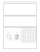
box, motor or brake components be sure to match model number of your unit to kit number below to ensure proper voltage requirements. Optional modifications and/or accessories included with your operator may add or remove certain components from these lists. Please consult a parts and service - LiftMaster GH | GH LOGIC VERSION 1 Manual - Page 17
ELECTRICAL BOX - ILLUSTRATED PARTS S4 S3 S9 S5 S7 S1 S6 S2 S8 7 8 L3 L1 L7 9 3 10 L5 L8 L6 L2 2 1 6 L2 L6 L4 4 5 17 - LiftMaster GH | GH LOGIC VERSION 1 Manual - Page 18
12586 OPERATOR(S) 115 Volt Models 230-460 Volt Models 575 Volt Models ITEM B1 B2 B3 B4 B5 B6 B7 B8 B9 B10 B11 PART # 07-10179 10-10190 10-10191 11-10192 11-10193 18-10194 31-10186 75-10184 75-11034 75-11035 75-11036 80-9001 87-P-062 DESCRIPTION Brake Hub Brake Release Lever Brake Disk Spring Cup - LiftMaster GH | GH LOGIC VERSION 1 Manual - Page 19
4 5 1 6 B10 D4 D11 D9 D12 D16 D15 D8 D5 D15 D13 D3 D7 D6 D1 D2 D10 H15 H9 H6 ILLUSTRATED PARTS 19 2 3 G2 D13 H13 H12 G1 H9 H4 H5 H15 B9 D15 D14 H15 H2 H9 H5 B7 H15 B3 B2 G3 H3 H8 B1 B4 B6 B5 H11 H7 B8 B11 H14 H1 H10 - LiftMaster GH | GH LOGIC VERSION 1 Manual - Page 20
must be placed between termianls 4 and 5. LISTED DOOR OPERATOR 3 BUTTON STATION OR 3 POSITION KEYSWITCH WITH SPRING RETURN TO CENTER AND STOP BUTTON STANDARD 7645 2 OR MORE 7645 KEY LOCKOUT 7645 Open Close Stop Open Close Stop Open Close Stop Open Close Stop Keyswitch 2 BUTTON STATION OR
-
 1
1 -
 2
2 -
 3
3 -
 4
4 -
 5
5 -
 6
6 -
 7
7 -
8
-
9
-
10
-
11
-
12
-
13
-
14
-
15
-
16
-
17
-
18
-
19
-
20
 |
 |
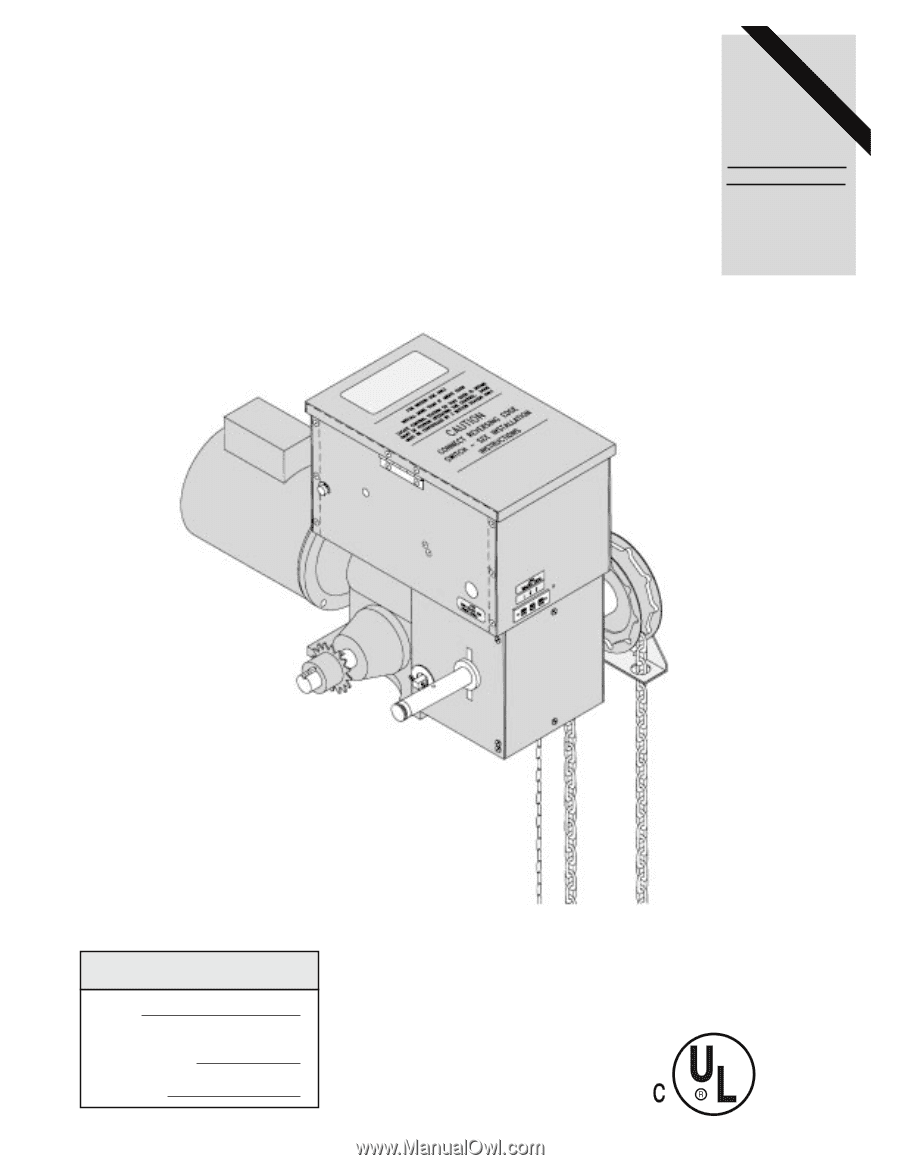
OWNER'S MANUAL
GH
SOLID STATE
INDUSTRIAL DUTY DOOR OPERATOR
LOGIC CONTROL
L
C2 Wiring
FACTORY SET
See pages 13 & 14
for other wiring
configurations
NOT FOR RESIDENTIAL USE
LISTED
DOOR
OPERATOR
41B6
Serial #
(located on electrical box cover)
Installation Date
Wiring Type
2
YEAR
WARRANTY