LiftMaster GH GH LOGIC VERSION 1 Manual - Page 2
Specifications, Mechanical, Safety, Motor, Electrical, Weights And Dimensions - 1 2 hp
 |
View all LiftMaster GH manuals
Add to My Manuals
Save this manual to your list of manuals |
Page 2 highlights
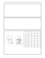
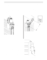
SPECIFICATIONS MOTOR TYPE Continuous duty HORSEPOWER 1/2, 3/4, 1, 1-1/2 Hp Single or Three phase 2 HP Three phase SPEED 1725 RPM VOLTAGE 115-230 Single phase 230 Three phase CURRENT See motor nameplate ELECTRICAL CURRENT VOLTAGE:.....5V dc AUXILIARY VOLTAGE: ...24V dc CONTROL STATION: .....NEMA 1 three button station. OPEN/CLOSE/STOP WIRING TYPE C2 (Standard) Momentary contact to OPEN/CLOSE/STOP plus wiring for sensing device to reverse and auxiliary devices to open and close with open override. (Other types available. See chart, Pg. 14) LIMIT ADJUST Linear driven, fully adjustable screw type cams. Adjustable to 30 feet. MECHANICAL DRIVE REDUCTION 40:1 Reduction Heavy duty bronze worm gear reducer OUTPUT SHAFT SPEED: .....43 R.P.M. DOOR SPEED 4 - 10" per sec. depending on door BRAKE Solenoid actuated disc brake HOIST WHEEL Standard mounting on left or right side SAFETY DISCONNECT Floor level chain hoist with electrical interlock for emergency manual door operation CLUTCH: (optional)....Adjustable torque limiter type REVERSING EDGE:.....(Optional) Electric or pneumatic sensing device attached to the bottom edge of door. A REVERSING EDGE IS STRONGLY RECOMMENDED FOR ALL COMMERCIAL OPERATOR INSTALLATIONS. REQUIRED WHEN THE 3 BUTTON CONTROL STATION IS OUT OF SIGHT OF DOOR OR ANY OTHER CONTROL (AUTOMATIC OR MANUAL) IS USED. WEIGHTS AND DIMENSIONS HANGING WEIGHT: .........80-110 LBS. 14.00" A Y See Note #2 B See Note #1 X C Hand Chain Wheel HP PHASE A 1/2 1 11-1/2 3/4 1 12-1/2 D 1 1 12-3/4 1-1/2 1 12-3/4 Y 1/2 3 11 3/4 3 11 1 3 12 1-1/2 3 12-1/2 See 2 Note #3 3 3 12-3/4 3 13-1/4 DIMENSIONS B C D 25-3/4 12-63/64 3 26-3/4 12-63/64 3 27 12-63/64 3 27 13-63/64 3-1/2 25-1/4 12-63/64 3 25-1/4 12-63/64 3 26-1/4 12-63/64 3 26-3/4 13-63/64 3-1/2 27 13-63/64 3-1/2 28-5/8 15-15/64 3 NOTES: 1) Output Shaft with 1" x 1/4" Key for 1/2 thru 2Hp operators, 1-1/4" x 1/4" Key for 3Hp operators. 2) MT'G CENTERS: X = 4-3/4"; Y = 5-1/2" for 1/2 thru 2Hp operators X = 7-17/32"; Y = 9-1/16" for 3Hp operators 3) Hand Chain Wheel extends 1-5/8" beyond operator in vertical mounting position as shown. 2
-
 1
1 -
 2
2 -
 3
3 -
 4
4 -
 5
5 -
 6
6 -
 7
7 -
 8
8 -
9
-
10
-
11
-
12
-
13
-
14
-
15
-
16
-
17
-
18
-
19
-
20
 |
 |